EasyManua.ls Logo

DSC PowerSeries PC1832 - User Manual

DSC PowerSeries PC1832
28 pages
Print Icon
To Next Page IconTo Next Page
Loading...
WARNING: This manual contains information on limitations regarding
product use and function and information on the limitations as to liability of
the manufacturer. The entire manual should be carefully read.
PC1616/PC1832/PC1864
User Manual
v4.6 and higher

Other manuals for DSC PowerSeries PC1832

Questions and Answers

  • W
    williamwangAug 20, 2025
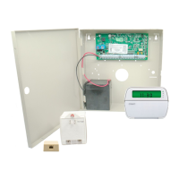
    How to fix AC Failure on DSC Control Panel?
    • J
      Jeremy FloydAug 20, 2025
      If you are experiencing an AC failure with your DSC Control Panel, verify that the voltage measured across the AC terminals is between 16-18VAC. If it is not, you may need to replace the transformer.
  • D
    David BrownAug 21, 2025
    What to do if my DSC PowerSeries PC1832 Control Panel has a low battery?
    • J
      Jessica ClarkAug 22, 2025
      If your DSC Control Panel displays a low battery warning, it could be due to the main panel battery voltage being less than 11.1VDC. Note that the trouble condition will not clear until the battery voltage is at least 12.5VDC under load. If the battery is new, allow one hour for it to charge. Verify the voltage measured across the AC terminals is 16-18 VAC, and replace the transformer if needed. Disconnect the battery wire leads and verify the battery charging voltage measured across the battery leads is 13.70 - 13.80 VDC. Connect the battery and remove AC power, then verify the measured voltage across the battery terminals is 12.5VDC minimum.
  • J
    jpatelAug 26, 2025
    What causes a PC5204 AC Failure on DSC Control Panel and how to resolve it?
    • A
      Amy WilliamsAug 26, 2025
      A PC5204 AC Failure on your DSC Control Panel indicates that there is no AC power at the PC5204 AC inputs. Verify the voltage measured across the AC terminals is 16-18VAC. Replace the transformer if required.
  • J
    Jennifer ForbesAug 27, 2025
    Why does my DSC Control Panel show PC5204 Low Battery?
    • D
      David BowmanAug 28, 2025
      If your DSC Control Panel is showing a PC5204 Low Battery warning, it means the PC5204 battery voltage is less than 11.5VDC. Note that this trouble condition will not clear until the battery voltage reaches 12.5VDC minimum, under load. Please refer to the 'Low Battery' troubleshooting steps.
  • T
    Tami MccallAug 30, 2025
    What to do when DSC PowerSeries PC1832 indicates Wireless Device Low Battery?
    • C
      Charles LopezAug 30, 2025
      If your DSC Control Panel indicates a Wireless Device Low Battery, it means that one or more wireless devices has a low battery. Replacing the batteries will cause a tamper. Replacing the cover will restore the tamper, causing the associated reporting codes to be sent to the Central Station.
  • J
    jonathon37Sep 3, 2025
    Why is my DSC Control Panel showing a Telephone Line Trouble?
    • L
      lesliethomasSep 3, 2025
      If your DSC Control Panel is displaying a telephone line trouble, it means the phone line voltage at TIP, RING on the main panel is less than 3VDC. To troubleshoot, measure the voltage across TIP and RING on the panel. Without any phone off-hook, it should be approximately 50VDC. With any phone off-hook, it should be approximately 5VDC. Try wiring the incoming line directly to TIP and RING. If the trouble clears, check the wiring or the RJ-31 phone jack.
  • J
    jessica36Sep 5, 2025
    How do I fix a Bell Circuit issue on my DSC PowerSeries PC1832?
    • H
      Heather MatthewsSep 5, 2025
      To fix a bell circuit issue on your DSC Control Panel, if there is an open circuit, disconnect the Bell-/Bell+ wire leads and measure the resistance of the wire leads. An open circuit indicates a break in the wiring or a defective siren/bell. Jumper Bell+, Bell- with a 1K resistor (Brown, Black, Red) and verify the trouble clears.
  • M
    Maria SmithSep 6, 2025
    What does 'General System Tamper' mean on my DSC Control Panel and how to fix it?
    • C
      Cheryl WilliamsSep 7, 2025
      A 'General System Tamper' message on your DSC Control Panel typically indicates that a tamper input on one or more modules is open circuit. To resolve this, short the tamper terminal to the COM terminal on unused modules connected to the KEYBUS (PC5100, PC5108, PC5200, PC5204, PC5208, PC5320, PC5400, PC5700).
  • B
    bryanschultzSep 9, 2025
    How to resolve a Module Supervision issue on DSC PowerSeries PC1832 Control Panel?
    • J
      Jessica StewartSep 9, 2025
      A module supervision issue on your DSC Control Panel means that the panel is not communicating with one or more modules on the KEYBUS, or a keypad is assigned to an incorrect slot. Modules are immediately enrolled and supervised when detected on the KEYBUS. If a module has been removed, or if the slot assignment of a keypad has been changed, module supervision must be reset. View the event buffer (via DLS or LCD5500 keypad) to identify the specific module(s) in trouble. To reset module supervision: Enter Program Section [902], press [#] (wait 1 minute for the panel to scan the KEYBUS), and then enter Program Section [903] to identify modules connected to the KEYBUS.
  • V
    Victoria AndersonSep 12, 2025
    What does it mean when my DSC PowerSeries PC1832 Control Panel displays 'RF Jam Detected'?
    • S
      Steven AndersonSep 12, 2025
      When your DSC Control Panel displays 'RF Jam Detected,' it indicates that the wireless receiver has detected excessive noise, possibly from external 433MHZ signal sources. You can check for these sources. To disable RF Jam detection, enable Option [7] in program section [804] subsection [90].

Summary

IMPORTANT SAFETY INSTRUCTIONS

REGULAR MAINTENANCE AND TROUBLESHOOTING

Cleaning the System

Instructions for cleaning the security equipment using a damp cloth only.

Troubleshooting System Errors

Guidance on identifying and resolving system errors or display messages.

About Your Security System

Carbon Monoxide Detection

Monitors carbon monoxide detectors and provides warnings if CO is detected.

Fire Detection Capability

Monitors fire detection devices like smoke detectors for fire conditions.

System Testing Requirements

Instructions for weekly system testing to ensure continued proper function.

Monitoring Functionality

Details the system's capability to transmit alarms to a central station.

System Maintenance Guidelines

Routine maintenance procedures for the security system, including battery care.

General System Operation Overview

Explains the system's components and how keypads display status and receive commands.

PowerSeries System Keypads

Keypad Display Symbols Explained

PK5500;RFK5500;RFK5564 Language Selection

Arming the System

Quick Exit Functionality

Disarming the System

Arming Modes and Special Functions

Stay Arming Explained

Arms perimeter zones while bypassing interior sensors for partial security.

Night and No-Entry Arming

Explains Night Arming and No-Entry Arming modes for enhanced security.

Remote Arming and Emergency Keys

Using wireless keys for control and activating emergency functions via keypad.

Handling Alarm Conditions

Intrusion and Fire Alarm Response

Procedures for responding to continuous siren (intrusion) and pulsed siren (fire) alarms.

Carbon Monoxide Alarm Procedures

Actions to take when a wireless carbon monoxide alarm is detected.

Time and Date Programming

Instructions for programming the system's current time and date settings.

Managing Zone Bypassing

Zone Bypassing Procedures

Step-by-step instructions for bypassing and unbypassing zones on various keypads.

Bypass Group Management

How to program and activate groups of zones for regular bypassing.

System Troubleshooting and Codes

Understanding Trouble Conditions

Explains system trouble indicators and lists common conditions with actions.

Alarm Memory and Door Chime

How to view alarm history and control the door chime feature.

Access Code Programming

Procedures for programming additional user access codes for system operation.

Advanced Access Code Management

Access Code Types and Attributes

Defines Master, Supervisor, and Duress codes, and their programmable attributes.

Programmable Attributes Explained

Details programmable attributes like Supervisor, Duress, and Bypass for user codes.

Access Code Configuration

Bell Squawk and Partition Assignment

Configures audible feedback for arming/disarming and assigns partition access to codes.

Erasing Access Codes and Notes

Procedures for erasing codes and important notes on access code programming.

User Function Commands

Accessing system functions like Auto-Arm/Disarm control and programming auto-arm time.

System Test and Remote Access

System Test Procedures

How to perform a system test to verify component functionality and battery status.

Remote Service and User Call-up

Enabling remote installer access and allowing the panel to call a downloading computer.

User Walk Test

Procedure for testing system detectors and notifying the central station.

Keypad Brightness and Contrast

Adjusting the visual settings of the keypad display.

Keypad Settings and Event Monitoring

Keypad Backlighting and Buzzer Control

Adjusting backlighting levels and buzzer volume on specific keypad models.

Viewing Event Buffer and Global Status

Accessing the system's event history and viewing partition status screens.

Sensor Reset Procedure

How to reset specific sensors after an alarm condition has occurred.

System Testing Procedures

Testing Keypad Sounder and Siren

How to test the system's sounder and siren outputs.

Testing Entire System Zones

Step-by-step guide for users to test all system zones and detectors.

Computer Access for System Updates

Procedure to enable the system for remote downloading by installers.

Reference Sheets and System Information

System Information Fields

Fields to record system details such as enabled functions, delay times, and contact information.

Access Code Record

A table for logging user and master access codes for PC1616, PC1832, and PC1864.

Sensor and Zone Configuration

Smoke and CO Detector Placement Guidelines

Smoke Detector Installation Recommendations

Guidance on locating smoke alarms outside sleeping areas and on each story.

CO Detector Placement Guidance

Recommendations for placing carbon monoxide detectors near sleeping areas.

Residential Smoke Alarm Installation Standards

Fire Safety and Escape Planning

Household Fire Safety Audit

Recommendations for conducting a household fire safety audit.

Developing a Fire Escape Plan

Steps and considerations for creating and rehearsing family fire escape plans.

Keypad Quick Guide

Understanding Keypad Status Lights

Explains the meaning of Ready, Armed, Trouble, and AC Power status indicators.

Keypad Function and Special Keys

Details the usage of Function keys (Stay, Away) and Special keys (Language, Emergency).

Common User Commands

Overview of essential user commands for system operation and status checks.

Advanced User and Installer Functions

User Options and Commands

Accessing system options like Event Buffer, System Test, and Time/Date.

PGM Commands and Installer Programming

Using PGM commands and accessing installer programming for advanced setup.

No-Entry Arming and Quick Exit

Explains No-Entry Arming and Quick Arm/Quick Exit functions.

Critical Safety Warnings and Precautions

System Reliability and Failure Points

Discusses system failures due to installation, power, batteries, and component issues.

Security Risks and Intruder Tactics

Covers criminal knowledge, intruder access methods, and wireless device compromise.

Operational and Environmental Factors

Addresses user response time, warning device effectiveness, and telephone line issues.

Importance of Testing and Maintenance

Emphasizes regular system testing and maintenance for optimal operation.

Regulatory Compliance and Notices

FCC and Industry Canada Compliance

Statements on FCC Part 15, Part 68, and Industry Canada technical specifications compliance.

Telephone Network Interaction and Maintenance

Information on telephone line connection requirements, potential harm, and service contacts.

End-User License Agreement (EULA)

Software License Grant and Usage

Details the rights and limitations for installing and using the DSC software product.

Warranty and Legal Disclaimers

Covers limitations of liability, disclaimers of warranties, and export restrictions.

DSC PowerSeries PC1832 Specifications

General IconGeneral
Zones8 on-board, expandable to 32
User Codes48
Keypads SupportedUp to 8
Operating Voltage16.5VAC
Backup Battery12VDC, 7Ah
PGM Outputs2
Wireless Zones32 (requires wireless receiver)
Auxiliary Power Output500 mA @ 12 VDC
Bell Output700mA @ 12VDC (PTC protected)

Related product manuals