Do you have a question about the DSC PC2585 and is the answer not in the manual?
Discusses potential reasons for alarm system malfunctions.
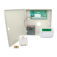
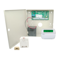
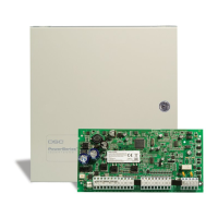
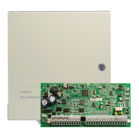
Details on the PC2585 control panel's features and capabilities.
Technical details of the system's digital communicator.
Panel programmability via keypad using EEPROM memory.
Monitoring capabilities for various system trouble conditions.
Procedures and requirements for initial system bench testing.
Details for connecting various panel terminals like AC, AUX, BELL.
Sequence of steps for powering up the alarm system.
Procedures for performing system tests and verifying functionality.
Default code and its functions for system control and programming.
Default code for accessing installer programming mode.
Procedures and conditions for arming the alarm system.
Procedures for correctly disarming the alarm system.
Entering the installer programming mode.
Defining zone types, delays, and other operational parameters.
Setting system times including entry/exit delays and test intervals.
Configuring basic system options via zone light settings.
Configuring additional system options.
Configuring options related to auto-arming and bypass.
Configuring zone loop types and panic key behavior.
Configuring force arming, tamper, and engineer reset settings.
Configuring fire zone behavior and keypad timeouts.
Setting alarm limits and transmission/bell delays.
Defining communication formats, handshakes, and data rates.
Directing transmissions to specific communication buffers.
Configuring programmable outputs and auxiliary input.
Setting system clock, auto-arm/disarm, and test transmission times.
Programming the primary Master Code for system access.
| Brand | DSC |
|---|---|
| Model | PC2585 |
| Category | Control Panel |
| Language | English |





 Loading...