1
1.1 Specifications
Downloading Software Support
• PC585 uses DLS-1 v6.5 and up.
Flexible Zone Configuration
• Four fully programmable zones; system expandable to eight
zones using keypad zone inputs and wireless zones
• 38 access codes: one master code, one maintenance code,
two duress codes, two supervision codes and 32 general
access codes
• 27 zone types; 8 programmable zone attributes
• Normally closed, single EOL and double EOL zone wiring
• Eight wireless zones available using the PC5132 Wireless
Receiver
Audible Alarm Output
• 700mA Supervised Bell Output (current limited at 3 amps),
12VDC
• Steady or Pulsed Output
EEPROM Memory
• Does not lose programming or system status on complete AC
and Battery failure
Programmable Outputs
• Two programmable voltage outputs; 18 programmable options
• PGM1 = 300mA; PGM2 = 50mA
Powerful 1.5 Amp Regulated Power Supply
• 550 mA Auxiliary Supply, 12 V
DC
• Positive Temperature Coefficient (PTC) components replace
fuses
• Supervision for loss of AC power, low battery
• Internal clock locked to AC power frequency
Power Requirements
• Transformer = 16.5 VAC, 1.5A
• Battery = 12 volt 4 Ah minimum rechargeable sealed lead
acid battery
Remote Keypad Specifications
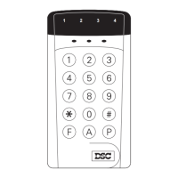
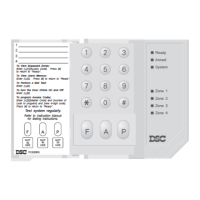
• Three keypads available:
- PC1555RKZ eight zone LED keypad with zone input
- PC5508Z eight zone LED keypad with zone input
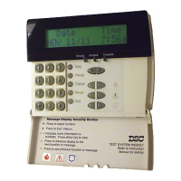
- LCD5500Z Alphanumeric keypad with zone input
• All keypads have five programmable function keys
• Connect up to eight keypads
• 4-wire (Quad) connection to Keybus
• Built in piezoelectric buzzer
Digital Communicator Specifications
• Supports major communication formats including SIA and
Contact ID
• Event-initiated personal paging
• Three programmable telephone numbers
• Two account numbers
• Supports LINKS1000 cellular communication
• Supports LINKS2X50 Long Range Radio Transmitter
• DTMF and pulse dialing
• DPDT line seizure
• Anti-jam feature
• Split reporting of selected transmissions to each telephone
number
System Supervision Features
The PC585 continuously monitors a number of possible trouble
conditions including:
• AC power failure
• Trouble by zone
• Tamper by zone
• Fire trouble
• Telephone line trouble
• Failure to communicate
• Low battery condition
• Bell output trouble
• Module fault (supervisory or loss of internal clock)
• AUX Power Supply Trouble
False Alarm Prevention Features
• Audible Exit Delay
• Audible Exit Fault
• Communication Delay
• Urgency on Entry Delay
• Quick Exit
• Cross Zone Burglary Alarm
• Rotating Keypress Buffer
Additional Features
• Auto Arm at specified time
• Keypad-activated alarm output and communicator test
• All modules connect to the system via a four wire Keybus up
to 1000’/305m from main panel
• An event buffer which records the past 128 events with both
the time and date at which they occurred; buffer can be
printed using PC5400 serial interface module, or viewed with
the LCD5500Z keypad.
• Supports the addition of the PC5132 Wireless receiver for
integration of wireless devices
• Uploading and downloading capability
• Local downloading capability through the use of the PC-LINK
adaptor
• Added Keybus fault protection: clock and data outputs have
been programmed to withstand shorts to +12v to prevent
control panel damage
System Introduction
S E C T I O N 1