G E T T I N G S T A R T E D
4
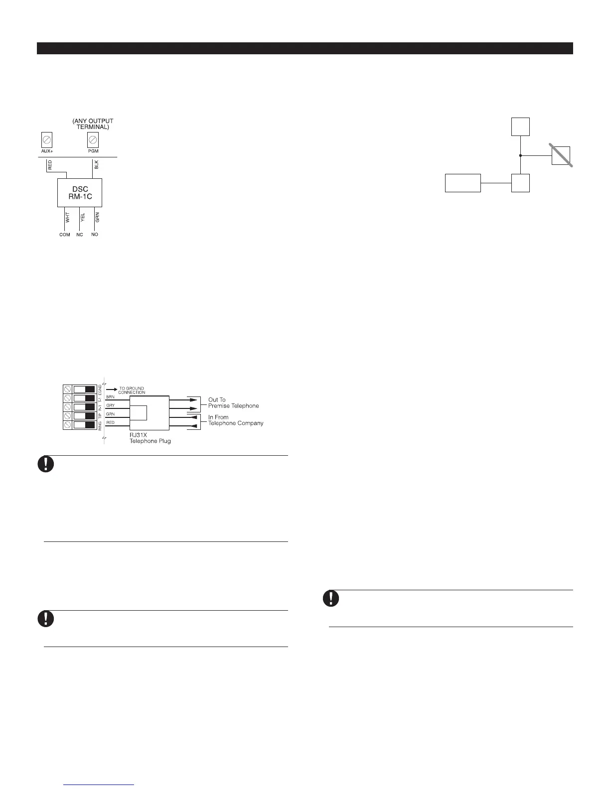
Programmable Output Terminals – PGM1 and
PGM2
Each PGM output is designed so that when activated by the
panel, the terminal will switch to ground.
PGM1 can sink up to 300mA of current.
Connect the positive side of the LED or
buzzer to AUX+, the negative side to
PGM1. If more than 300 mA of current are
required, a relay must be used. Please
study PGM wiring in the accompanying
diagram.
PGM2 operates similarly to PGM1.
However, PGM2 can only sink up to 50mA
of current. For a list of the programmable
output options, please see Section 5.11
“PGM Output Options.”
Zone Input Terminals – Z1 to Z4
Each detection device must be connected to a zone on the
control panel. We suggest that one detection device be
connected to each zone; wiring multiple detection devices to a
single zone, however, is possible. For zone wiring specifics,
please see Section 2.8 (“Zone Wiring”).
Telephone Connection Terminals –
TIP, RING, T-1, R-1
If a telephone line is required for central station communication
or downloading, connect an RJ-31X telephone jack in the
following manner:
For proper operation, no other telephone equipment
should be connected between the control panel and
the telephone company facilities
.
Do not connect the
alarm panel communicator to telephone lines
intended for use with a fax machine. These lines may
incorporate a voice filter which disconnects the line
if anything other than fax signals are detected,
resulting in incomplete transmissions
.
2.3 Keybus Operation and Wiring
The Keybus is used by the panel to communicate with all
connected modules and vice versa. The red (AUX+) and black
(AUX-) terminals are used to provide power, while the yellow
(YEL) and green (GRN) terminals are clock and data respectively.
The four Keybus terminals of the panel must be
connected to the four Keybus terminals or wires
of all modules.
The following restrictions apply to Keybus wiring:
• Keybus should be run in minimum 22 gauge quad (0.5mm);
two pair twist is preferred.
• The modules should be home-run to the panel but can be
connected in series or T-tapped.
• Any module can be connected anywhere along the Keybus. You
do not need to run a separate Keybus wire for keypads, etc.
• No module can be more than 1,000'/305m (in wire length)
from the panel.
• Shielded wire should not be used.
Example of Keybus Wiring
NOTE:
Module (A) is correctly
wired within 1,000'/305m of
wire from the panel.
Module (B) is correctly
wired within 1,000'/305m of
wire from the panel.
Module (C) is NOT wired correctly as it is further than 1,000'/
305m from the panel, in wire distance.
2.4 Current Ratings – Modules and
Accessories
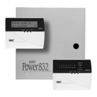
In order for the PC585 system to operate properly, the power output
capabilities of the main control and the expansion devices must not
be exceeded. Use the data presented below to ensure that no part
of the system is overloaded and cannot function properly.
PC585 (12 V
DC)
AUX
+
: ........... 550mA: Subtract the listed rating for each keypad,
expansion module and accessory connected to
AUX
+
or Keybus.
BELL: ...........700mA continuous rating; 3.0A short term.
Available only with standby battery connected.
PC585 Device Ratings (at 12 VDC)
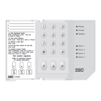
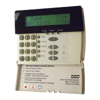
• LCD5500Z Keypad: 75-85mA
• PC1555RKZ Keypad: 75-85mA
• PC5508Z Keypad: 75-85mA
• PC5400 Serial Module: 65mA
• PC5132 Wireless Receiver: 125mA
Other Devices
Please read the manufacturer’s literature carefully to determine
the maximum current requirements for each device—during
activation or alarm—and include the proper values for loading
calculations. Connected devices must not exceed system
capabilities during any possible operational mode.
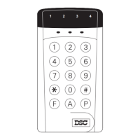
2.5 Keypad Assignment
There are eight available slots for keypads. LED keypads by
default are always assigned to slot 1. LCD5500Z keypads are
always assigned to slot 8. You will need to assign each keypad
to its own slot (1 to 8). Keypad assignment is required, as it tells
the panel which slots are occupied. The panel can then generate
a fault when a keypad supervisory is not present.
One LCD keypad must be assigned to slot 8 in
order to upload keypad programming using
DLS-1 software.
How to Assign Keypads
Do the following at each keypad installed on the system:
1. Enter [✱][8][installer’s code] to go to installer programming
2. Enter [000] for Keypad Programming
3. Enter [0] for Slot Assignment
4. Enter a two digit number (11-18) to specify which supervisory
slot the keypad will occupy.
5. Press [#] twice to exit installer programming.
B
C
A
PANEL
500’
500’
150’
150’
B
C
A
PANEL
500’
500’
150’
150’