SYSTEMVINTRODUCTION
2
1.2 Additional Devices
In addition to the information below, see the back cover for a
DSC module compatibility table.
PC5132 Wireless Receiver
The PC5132 Wireless Receiver can be used to connect up to 8
wireless devices to the system. All devices are spread spectrum,
900 MHz, fully supervised devices which use standard ‘AAA’ or
‘AA’ alkaline batteries
.
Seven additional devices are available. They are as follows:
WLS904 Wireless Motion Detector
WLS905 Wireless Universal Transmitter
Adds wireless door or window contacts to your system.
WLS906 Wireless Smoke Detector
WLS907 Wireless Slimline Universal Transmitter
A smaller wireless door or window contact.
WLS908 Wireless Panic Pendant
Adds personal protection to the system. When used, the unit will
indicate a non-medical emergency to the central station.
WLS909 Wireless Key
Adds a simple and mobile method of arming and disarming to the
system, as well as one-button access to several programmable
functions.
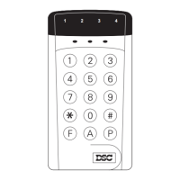
WLS910 Wireless Handheld Keypad
PC5400 Printer Module
The PC5400 Printer Module will allow the panel to print out all
events that occur on the system to any serial printer. The
printout will contain the time, date and the event that occurred.
LINKS1000 Cellular Communicator
The LINKS1000 Cellular Communicator can be used three
different ways: as the sole communicator for the panel, as a
backup for either or both telephone numbers or as a redundant
backup to the land line communicator where the panel will call
both the land line and via the LINKS.
LINKS2X50
Either the LINKS2150 or LINKS2450 may be used to transmit
alarm information over a long range radio network.
Cabinets
Several different cabinets are available for the PC585 modules.
They are as follows:
PC5003C Cabinet
Main control cabinet for the PC585 main panel. Dimensions
288mm x 298mm x 78mm / 11.3” x 11.7” x 3” approximately.
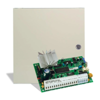
PC500 Cabinet
Main control cabinet for the PC585 main panel. Dimensions
213mm x 235mm x 78mm / 8.4” x 9.25” x 3” approximately.
PC5004C Cabinet
Cabinet to house the PC5400 Printer Module. Dimensions
229mm x 178mm x 65mm / 9” x 7” x 2.6” approximately.
1.3 Out of the Box
Please verify that the following components are included in
your system:
• one PC500 main control cabinet
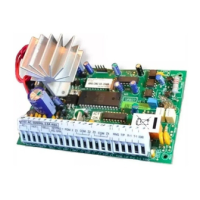
• one PC585 main control circuit board
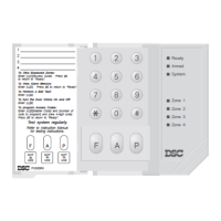
• one PC1555RKZ keypad with zone input
• one Installation Manual with programming worksheets
• one Instruction Manual for the end user
• one hardware pack consisting of:
- one mylar cabinet label
- four plastic circuit board standoffs
- ten 5600Ω (5.6K) resistors
- one 2200Ω (2.2K) resistor
- one 1000Ω (1K) resistor
- ground connection assembly
- one cabinet door plug