G E T T I N G S T A R T E D
6
This option can only be selected if Normally
Closed (NC) detection devices or contacts are
being used.
Only one NC contact can be connected to each
zone. Wiring multiple detection devices or con-
tacts on a single loop is not allowed
.
The following chart shows zone status under certain conditions:
Loop Resistance Loop Status
0Ω (shorted wire, loop shorted) Fault
5600Ω (contact closed) Secure
Infinite (broken wire, loop open) Tamper
11200Ω (contact open) Violated
○○○○○○○○○○○○○○○○○○○○○○○○○○○○○○○○
End of Line Resistors ..................................Section [013]: [1]
○○○○○○○○○○○○○○○○○○○○○○○○○○○○○○○○
Double End of Line Resistors......................Section [013]: [2]
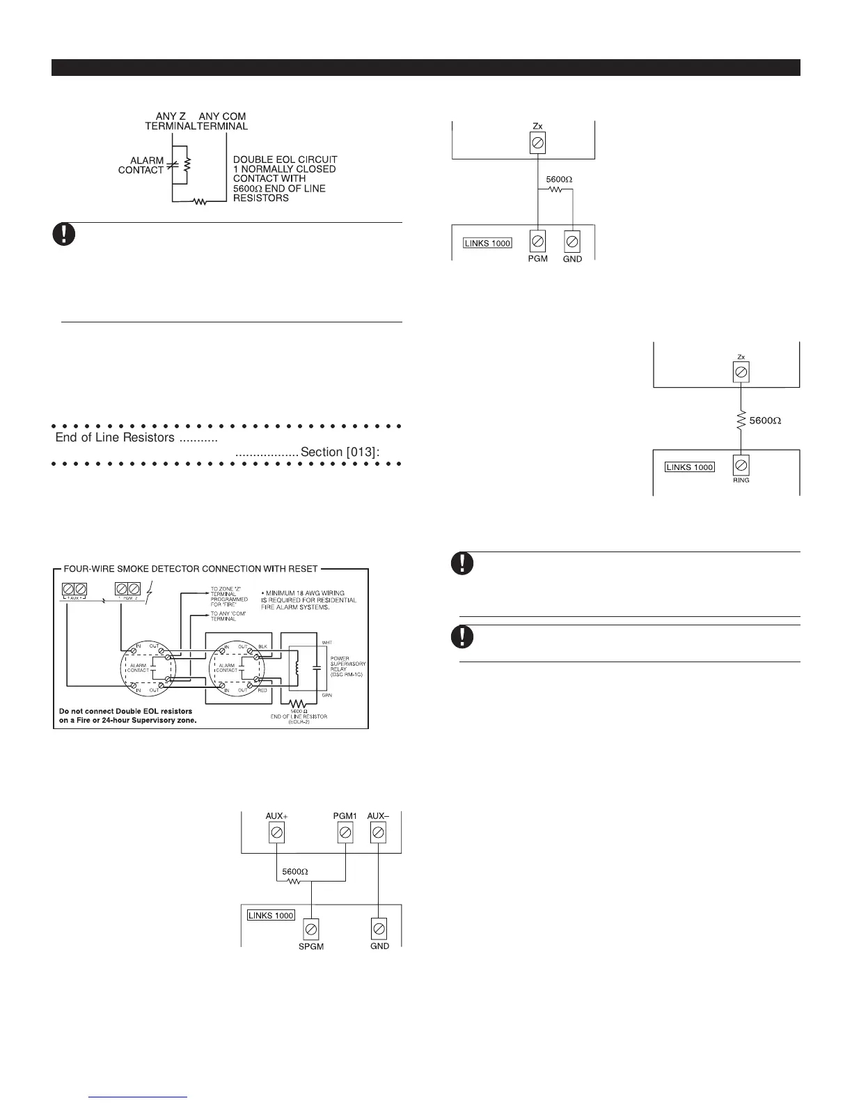
2.9 Fire Zone Wiring
4-Wire Smoke Detectors
All fire zones must be wired according to the following diagram:
2.10 LINKS Zone Wiring
LINKS Support
When using the LINKS1000
cellular communicator, connect
the LINKS to the main panel
according to the diagram.
LINKS Supervision (24 Hour Supervisory)
When using the LINKS1000
cellular communicator, any main
board zone may be configured
for LINKS Supervision. Program
this zone as zone type [09], 24
Hour Supervisory in section
[001].
With a LINKS Supervisory zone,
if the LINKS1000 experiences a
trouble, the zone will be violated,
causing the panel to report the event to the central station. This
type of zone
always
requires a single EOL resistor (5600Ω).
Wire this zone according to the above diagram.
LINKS Answer
When using the LINKS1000 cellular
communicator, any main board
zone may be configured for LINKS
Answer.
A zone configured for LINKS Answer
allows downloading to be
performed in the event of telephone
line failure. When the LINKS
receives a telephone call, it will
activate the RING terminal on the
LINKS circuit board. The zone programmed as LINKS Answer
always
requires a single EOL resistor (5600Ω).
Wire the LINKS Answer zone according to the above diagram.
The LINKS Answer zone is only required for
downloading to the panel via the LINKS.
When using the LINKS, Busy Tone Detection must
not be used.
Keypad zones cannot be used for 24 Hour Super-
visory or LINKS Answer.
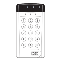
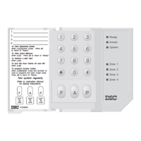
2.11 Keypad Zones
Each “z” keypad on the system has a zone input to which a
device - such as a door contact - can be connected. This saves
you from running wires back to the control panel for every
device.
To install the keypad, open the keypad plastic by removing the
screw at the bottom of the unit. Locate the five terminals on the
keypad circuit board. Connect the four Keybus wires from the
control panel: the red wire to R, the black to B, the yellow to Y
and the green to G.
To connect the zone, run one wire to the Z terminal and the other
to B. For powered devices, use red and black to supply power
to the device. Run the red wire to the R (positive) terminal and
the black wire to the B (negative) terminal.
When using end of line supervision, connect the zone according
to one of the configurations outlined in Section 2.8 “Zone
Wiring.” End of line resistors must be placed on the device
end of the loop, not at the keypad.