G E T T I N G S T A R T E D
5
After assigning all keypads, perform a supervisory reset by
entering section [902] in installer’s programming. The panel will
now supervise all assigned keypads and enrolled modules on
the system.
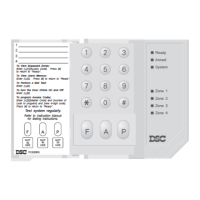
How to Program Function Keys
By default, the 5 function keys on each keypad are programmed
as Stay Arm (03), Away Arm (04), Chime (06), Quick Exit (14)
and Sensor Reset (16). You can change the function of each key
on every keypad:
1. Go to the keypad where you want to change the function key
programming and enter Installer Programming.
2. Press [000] for Keypad Programming.
3. Enter [1] to [5] to select a function key to program.
4. Enter the 2 digit number, [00] to [17] to select the feature you
want the function key to have. For a complete list of Function
Key options
See Section 3.5 “Function Keys” .
5. Continue from step 3 until all function keys are programmed.
6. To exit Installer Programming, press [#] twice.
2.6 Supervision
By default, all modules are supervised upon installation.
Supervision is enabled at all times so that the panel can indicate
a trouble if a module is removed from the system.
To check on which modules are currently connected and
supervised, enter programming section [903] from installer’s
programming. The LCD keypad will allow you to scroll through
the display of connected modules. A connected module which
does not show as being present will appear as a trouble
condition and the Trouble light on the keypad will turn ON. This
condition may be due to one or more of the following reasons:
• the module is not connected to the Keybus
• there is a Keybus wiring problem
• the module is more than 1,000'/305m from the panel
• the module does not have enough power
For more information regarding module supervision troubles,
please refer to Section 3.4 (“[
✱] [2] Trouble Conditions”).
2.7 Removing Modules
The panel must be instructed to no longer supervise a module
being removed from the system. To remove the module, disconnect
it from the Keybus and reset the supervision field by entering [902]
in the installer’s programming
.
The panel will be reset to recognize
and supervise all existing modules on the system.
2.8 Zone Wiring
For a complete description of the operation of all zone types,
please refer to Section 5.2 (“Zone Programming”).
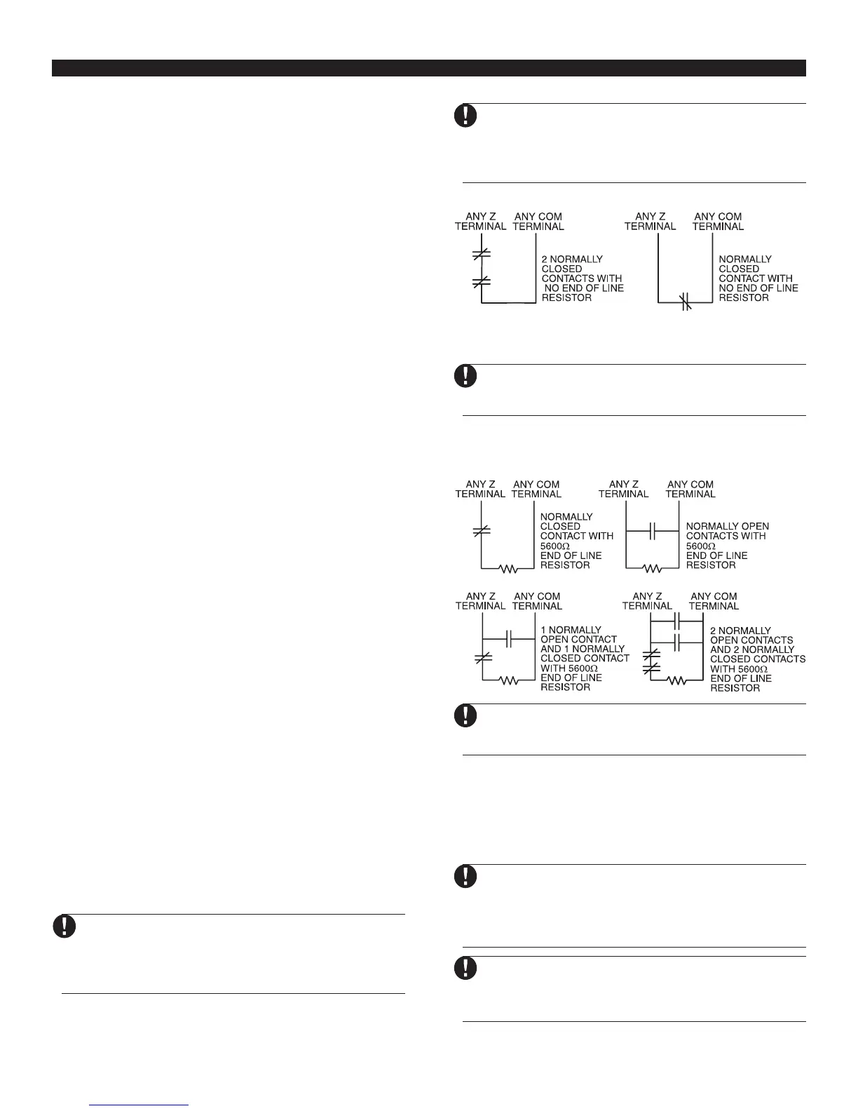
There are several different ways in which zones may be wired,
depending on which programming options have been selected.
The panel can be programmed to supervise normally closed, End
of Line, or Double End of Line loops. Please refer to the following
diagrams to study each type of individually supervised zone wiring.
Any zone programmed for Fire or 24 Hour Supervi-
sory must be wired with a single End of Line (EOL)
resistor regardless of the type of zone wiring
supervision selected for the panel (section [013]:
[1] -[2]). See Section 5.2 “Zone Programming.”
If you change the zone supervision options from
DEOL to EOL or from NC to DEOL (section [013],
options [1] or [2]), you should power down the
system completely, and then power it back up. If
you do not, the zones may not work correctly.
Normally Closed (NC) Loops
To enable normally closed loops, programming section [013],
option [1] must be ON.
This option should only be selected if Normally
Closed (NC) detection devices or contacts are
being used
..
..
.
Single End Of Line (EOL) Resistors (5600Ω)
To enable panel detection of single end of line resistors,
programming section [013], options [1] and [2] must be OFF.
This option should be selected if either Normally
Closed (NC) or Normally Open (NO) detection
devices or contacts are being used
.
Double End of Line (DEOL) Resistors
Double End of Line resistors allow the panel to determine if the
zone is in alarm, tampered or faulted.
To enable panel detection of double end of line resistors,
programming section [013], option [1] must be OFF and option
[2] must be ON.
If the Double EOL supervision option is enabled,
all hardwire zones on the main panel must be
wired for Double EOL resistors, except for Fire
and 24 Hour Supervisory zones.
Do not wire DEOL resistors on keypad zones.
Do not use DEOL resistors for Fire zones or 24
Hour Supervisory zones. Do not wire Fire zones
to keypad zone terminals if the DEOL supervision
option is selected.