20 DoorTec Deutschland | www.doortec.online
04/2022
-
Version 1
Änderungen vorbehalten | Subject to Modifications
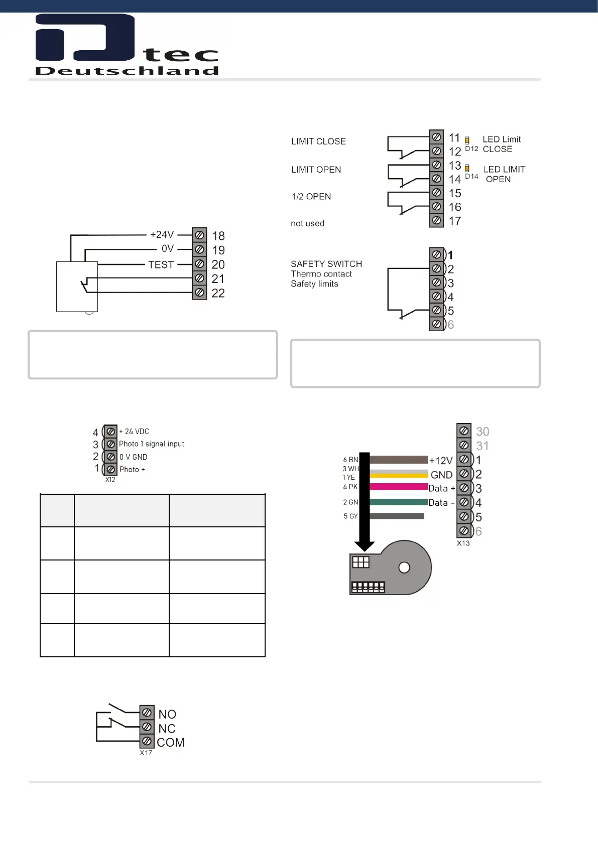
10.11 Limit switch - Mechanical limit switch
Parameter 11:00)
10.12 Limit Switch - Kostal Encoder
(Parameter 11:05, 11:06)
10.8 Photo Beam Reflex - Photo 2
(Testing required)
Colour code photo beam RAY-RT:
18: +24 V = brown
19: 0V = blue
20: Test = grey
21: Input = black
22: Input = white
10.9 Additional photo beam - Photo 1 / X12
(Parameter 31:01)
10.10 Potential Free Contact K3 (OPTION)
INFORMATION !
The polarity of the test signal must be considered. The
signal is switched to low (0V) while testing.
X12
Self contain pho-
to cell
Photocell with re-
lay output
4
+ Supply to re-
ceiver
+ Supply
3
+ Signal from re-
ceiver
Relay output
2
- common ground - common ground
1
+ Supply to trans-
mitter
Relay output
INFORMATION !
LED D12 / D 14 are activated when the respective end
position is reached.
not in use
Chain