A
B
C
D
E
F
G
H
L
M
N
P
Impianto di alimentazione / Scarico
Fuel system / Exhaust system
sezione / section
L 8
33Monster 400/620 - M.Y. 2004 - edizione/edition 00
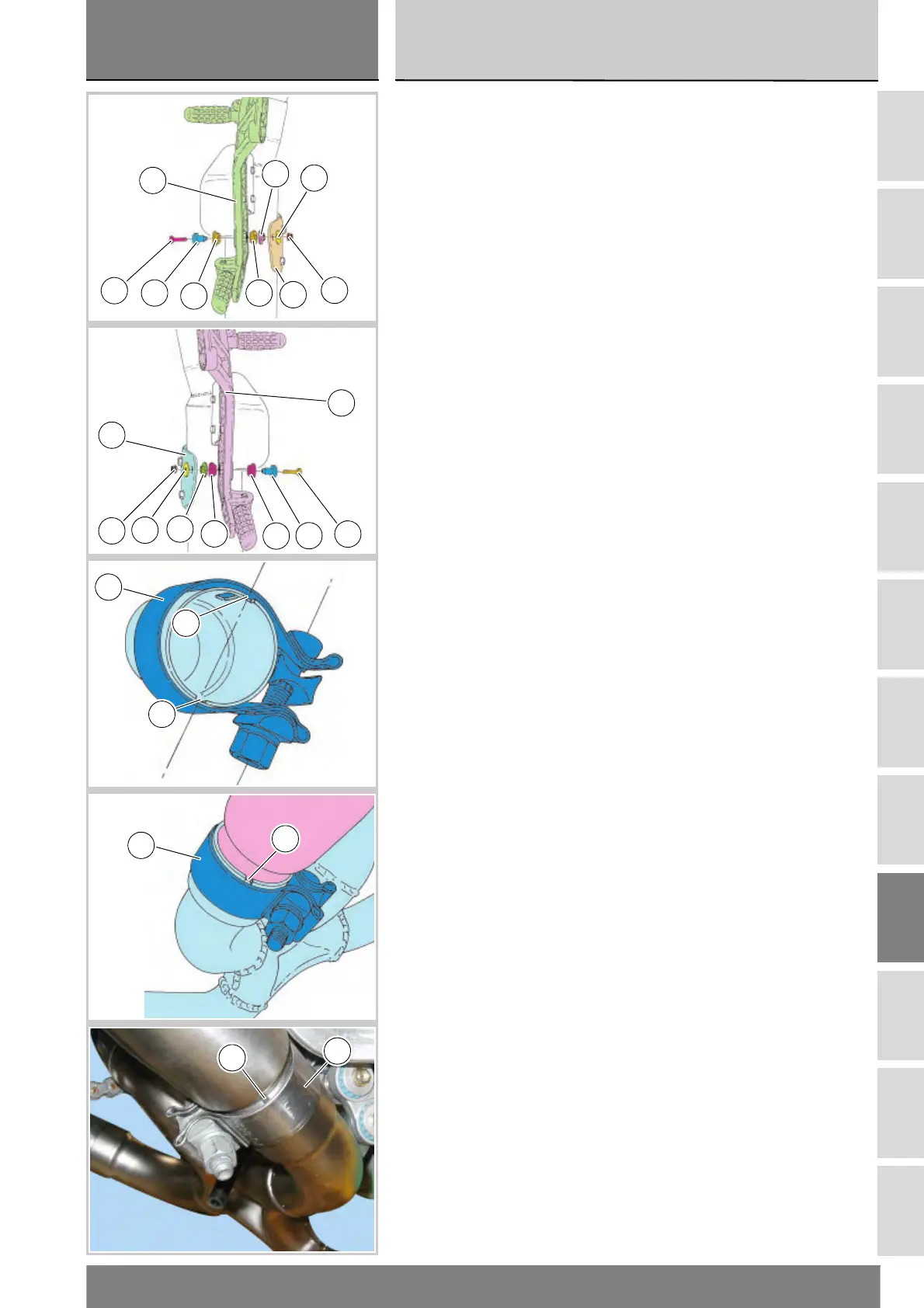
Se rimossi, installare i quattro
gommini antivibranti (9), orientandoli
ai due lati della piastra porta pedana
(A).
Inserire le boccole (20) nelle staffe
supporto silenziatore (19) e (13).
Portare le staffe supporto silenziatore
in appoggio contro le piastre porta
pedana (A) e inserire le boccole (10)
fino a battuta.
Inserire le viti (11) e, sul lato opposto,
inserire le rosette (14) e impuntare i
dadi (15).
Serrare le viti (11) alla coppia
prescritta (sez. C 3), contrastando i
dadi.
Per posizionare le fascette (8) di
fissaggio dei silenziatori allo scarico,
orientare le fascette in modo che le
viti risultino parallele all’asse passante
per gli scassi (B) dei tubi di scarico.
Posizionare le fascette (8) facendo in
modo che risultino a filo con i tubi di
scarico o comunque senza scoprire
interamente gli scassi (B).
Serrare le fascette (8) alla coppia
prescritta (Sez. C 3).
Install the four vibration damping
pads (9) – if they have been removed,
on both sides of the footpeg plate (A).
Fit the bushes (20) into the silencer
brackets (19) and (13).
Rest the silencer brackets against
footpeg plates (A) and insert the
bushes (10) fully home.
Insert the screws (11). Fit the
washers (14) at the opposite end and
snug the nuts (15) finger-tight.
Tighten the screws (11) to the
specified torque (Sect. C 3) hold the
nuts.
Position the clamps (8) retaining the
silencers to the exhaust pipe so that
the screws are parallel to the axis of
the exhaust pipe slots (B).
The clamps (8) should be flush with
the exhaust pipes and the slots (B)
should be partially covered.
Tighten the clamps (8) to the
specified torque (Sect. C 3).
11
10
19
15
14
20
A
9
9
15
14
20
13
10
11
A
9
9
8
B
B
B
8
B
8