A
B
C
D
E
F
G
H
L
M
N
P
Motore
Engine
sezione / section
N 4.2
33Monster 400 - 620 Aggiornamento/Update - M.Y. 2006 - edizione/edition 00
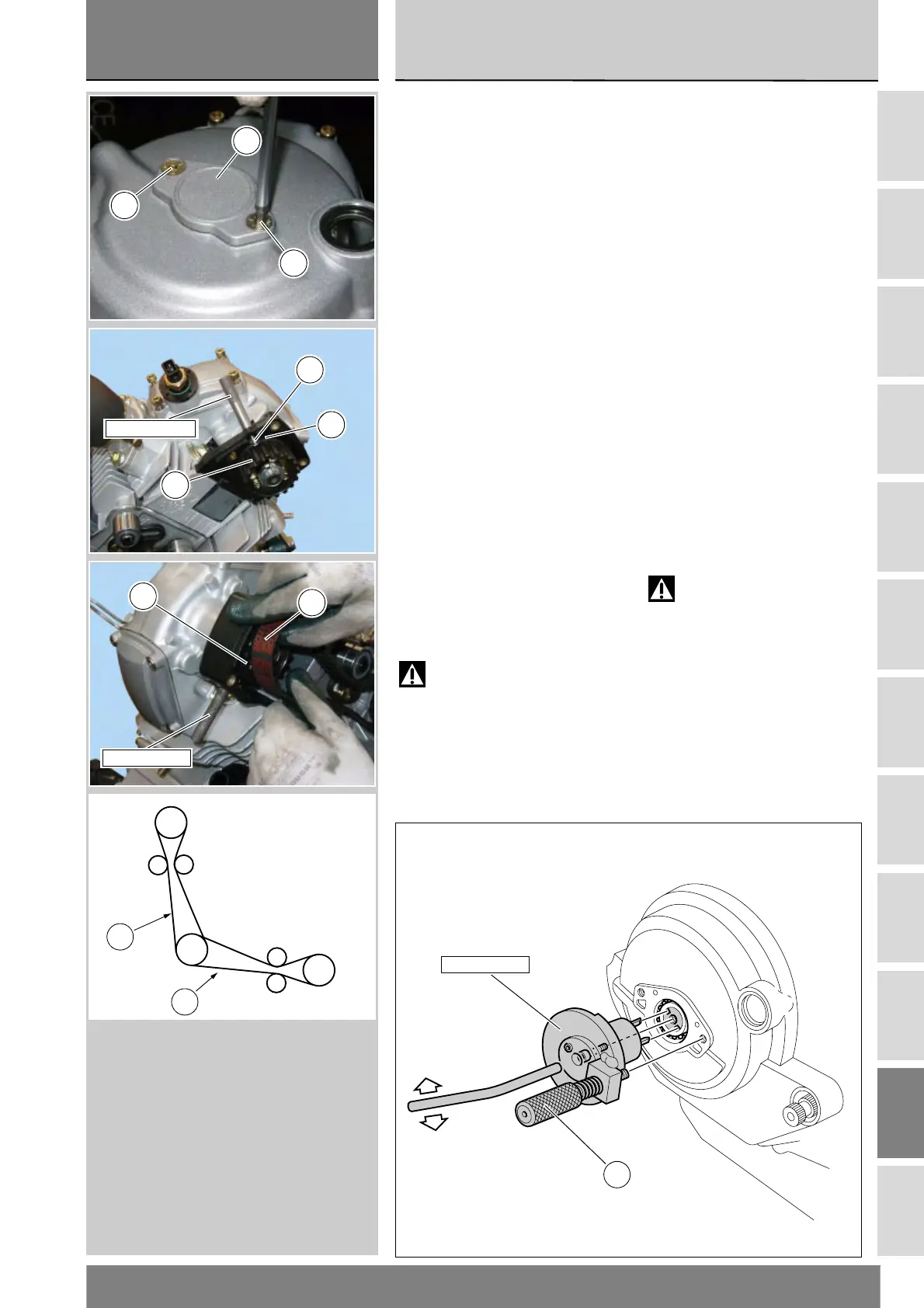
Unscrew the two screws (D) and
remove the small cover (C) from the
generator cover.
Fit the locking tool part no.
88713.2011 to the crankshaft and
tighten by hand pin (E) fully home.
Install the horizontal (9) and vertical
(28) timing belts manually. Do not use
any tools and do not disturb belt
rollers alignment.
Tighten the two tools part no.
88713.2009 as shown in the figure to
lock the flanges (17) of the horizontal
and vertical belt rollers (16). Tool ends
must locate into the flange slots.
Align the two timing marks (F) on belt
rollers (16) with the tool ends
88713.2009.
Check belt tension ad adjust, if
needed, as described under
“Checking and adjusting timing belt
tension” (Sect. D 5).
Warning
Check tension reading on the
belt sections (H) and (G) indicated in
the figure.
Rimuovere il coperchietto (C) dal
coperchio alternatore svitando le due
viti (D).
Installare l’attrezzo di bloccaggio
88713.2011 sull’albero motore e
serrare a fondo (manualmente) il
tampone (E).
Installare la cinghia distribuzione
orizzontale (9) e verticale (28)
utilizzando esclusivamente le mani
senza modificare l’allineamento delle
pulegge.
Bloccare le flange (17) delle pulegge
orizzontali e verticali (16) avvitando i
due attrezzi 88713.2009, come
indicato in figura. L’estremità degli
attrezzi devono inserirsi nelle cave
delle flange.
Allineare i due segni di fase (F) delle
pulegge (16) con le estremità degli
attrezzi 88713.2009.
Eseguire il controllo del valore di
tensionamento e la eventuale
registrazione come descritto al
paragrafo “Controllo e registrazione
tensione cinghie distribuzione” (Sez.
D 5).
Attenzione
Controllare il valore di
tensionamento sui bracci (H) e (G)
delle cinghie indicati in figura.
E
88713.2011
D
D
C
88713.2009
17
16
F
88713.2009
16
28
G
H
Verticale
Vertical
Mobile
Fisso
Fixed
Mobile
Orizzontale
Horizontal
Fisso
Fixed