23
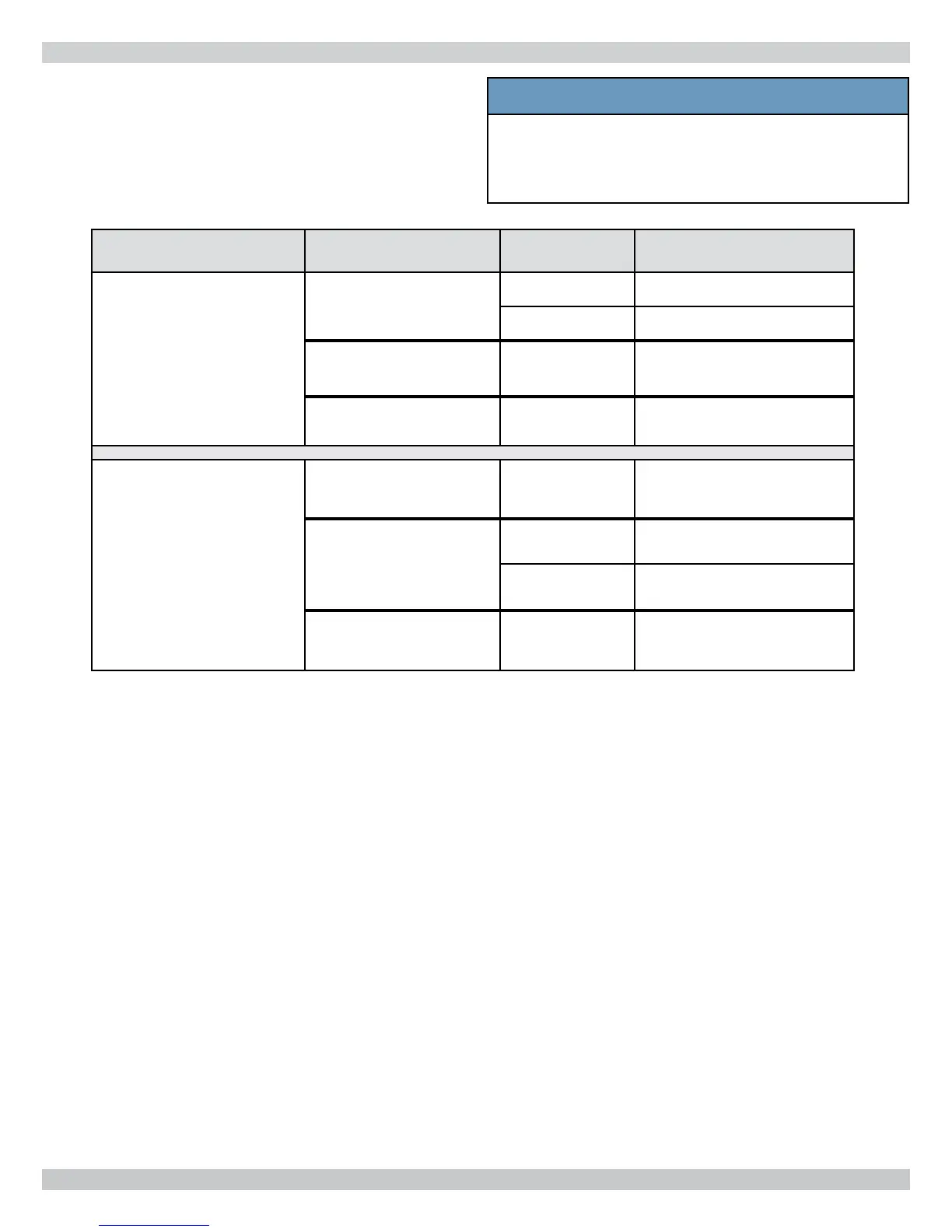
6.6 Venting Confi gurations
Various venting confi gurations can be applied to this boiler.
For guidance see Venting Confi guration Table 7 and
corresponding fi gures.
Flue Gas Location
Combustion Air
Location
Flue Gas
Terminals
Corresponding Figures
Roof
Roof
Two Pipe fi gure 6-1
Concentric fi gure 6-7
Side Wall Single Pipe fi gure 6-8
Inside Air Single Pipe fi gure 6-9
Side Wall
Roof Single Pipe fi gure 6-10
Side Wall
Two Pipe fi gures 6-2, 6-3
Concentric fi gures 6-4, 6-5, 6-6
Inside Air Single Pipe fi gure 6-11
Table 7 - Venting Confi gurations
6 - COMBUSTION AIR AND VENT PIPING
NOTICE
Use of vent covers may cause freezing. If using
vent covers overall vent length must be considered.
Failure to heed this information may compromise
operation of this boiler.