5 | Installation
100
D-R 290
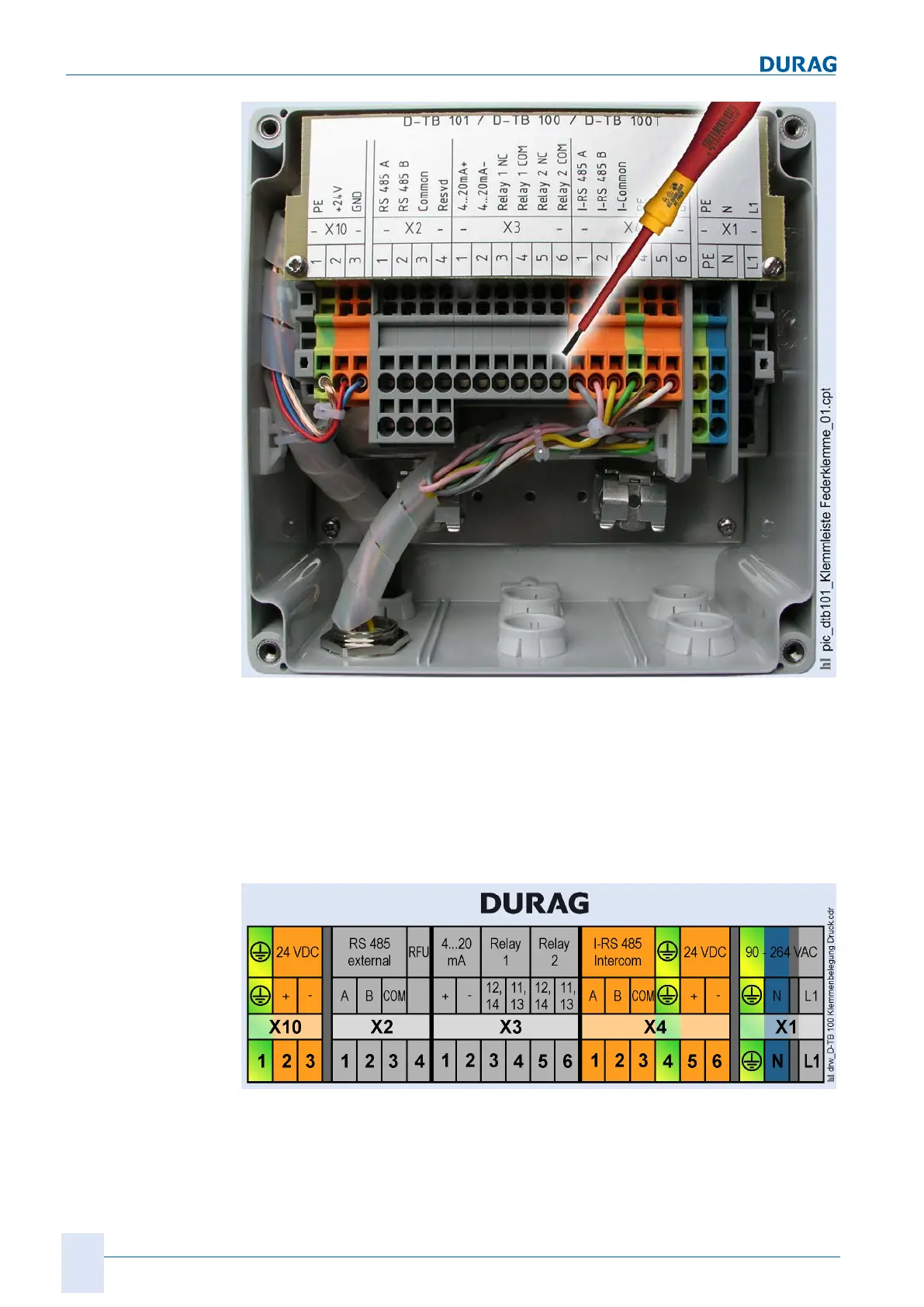
Fig. 5.34: Connecting the cable
1. For connection of the individual cores, the retaining springs in the terminal strip are
pushed back using a screwdriver. This is done by inserting the screwdriver into the
rectangular opening (see
Fig. 5.34 ) and bending the spring back.
2. The cores should be stripped back and provided with end sleeves, then inserted
into the round opening (below) as far as the stop.
3. Remove the screwdriver, and gently tug the core to check it is firmly seated.
For the customer's connections, the terminals X1, X2 and X3 (Fig. 5.34 and Fig. 5.35 )
are provided.
Fig. 5.35: D-TB 100 terminal box connection diagram
X1 is used to connect the D−TB 100 supply unit to the mains. Terminal X3 is used to
transmit the customer's analogue and status signals. X2 is for the customer's bus con
nection to the system.
Connections (by the
operating company)
 Loading...