5 | Installation
D-R 290
91
Purge air IN
c
Purge air OUT
c
Limit position closing shutter OPEN
Limit position closing shutter CLOSED
External shutter close
External shutter close
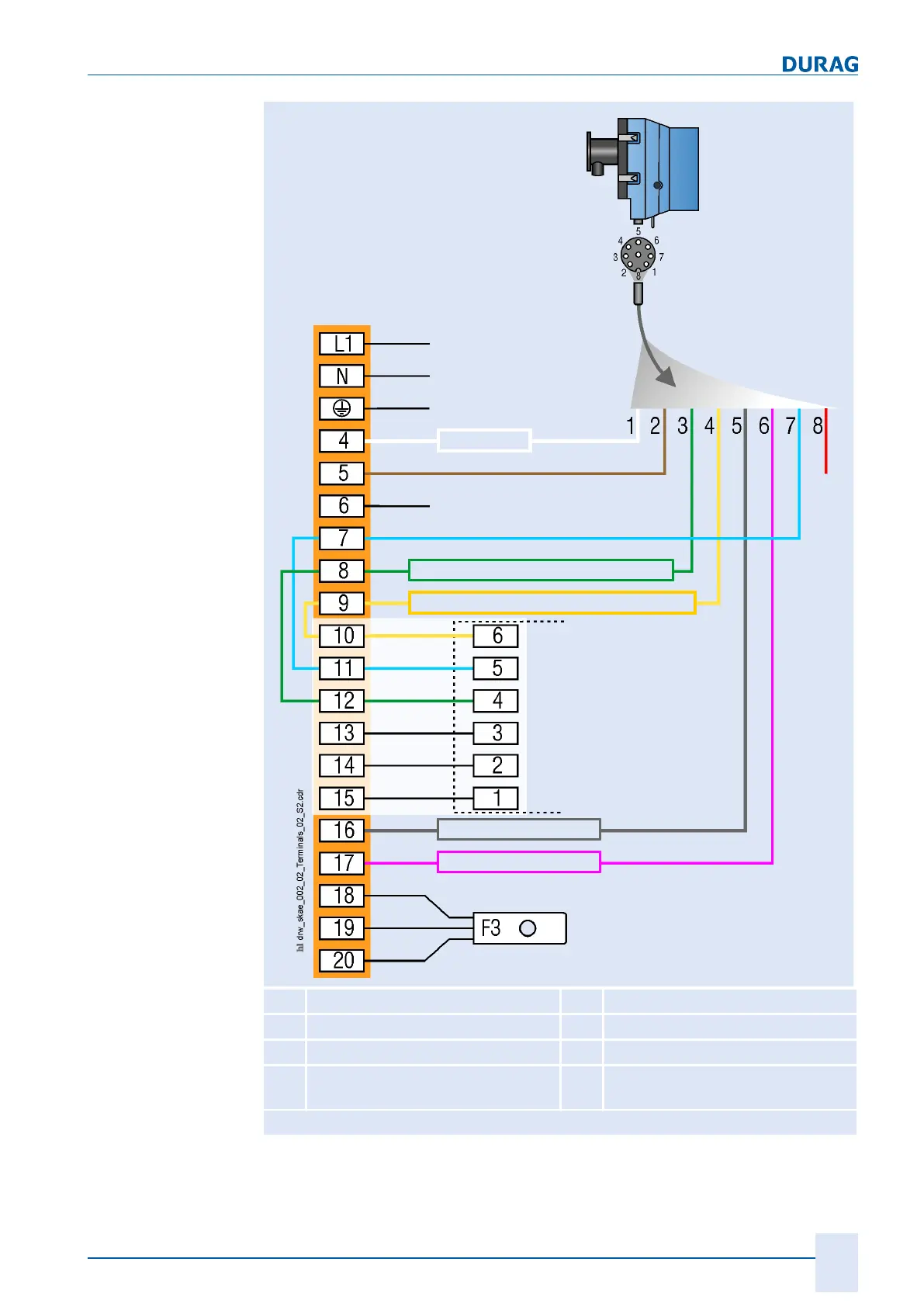
1 (white) 24 VDC sensor 2 (brown) Purge air inlet
3 (green) S1 inlet (SSK* open) 4 (yellow) S2 inlet (SSK* closed)
5 (grey) Outlet (SSK* open) 6 (lilac) Outlet (SSK* open)
7 (blue) GND 8 (red) 24 VDC SSK*
(not needed for D
−SK AE)
*SSK = Fail-safe shutter
Fig. 5.23: Connection of the fail-safe shutter to the 8-core plug cable of the measuring head
 Loading...