7 | Checking / setting parameters with D‑ESI 100
D-R 290
145
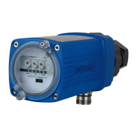
Pin Colour Function Pin Colour Function
1 wh 24 VDC sensor 5 gy Output (SSK open)
2 bn Input purge air 6 pk Output (SSK open)
3 gn Input S1 (SSK open) 7 bu GND
4 ye Input S2 (SSK closed) 8 rd 24 VDC SSK
Table 7.14: Pin assignment of the 8-pin plug for purge air monitoring
The warning thresholds and fault thresholds affect the behaviour of the device at
specific purge air values. These values should not be changed.
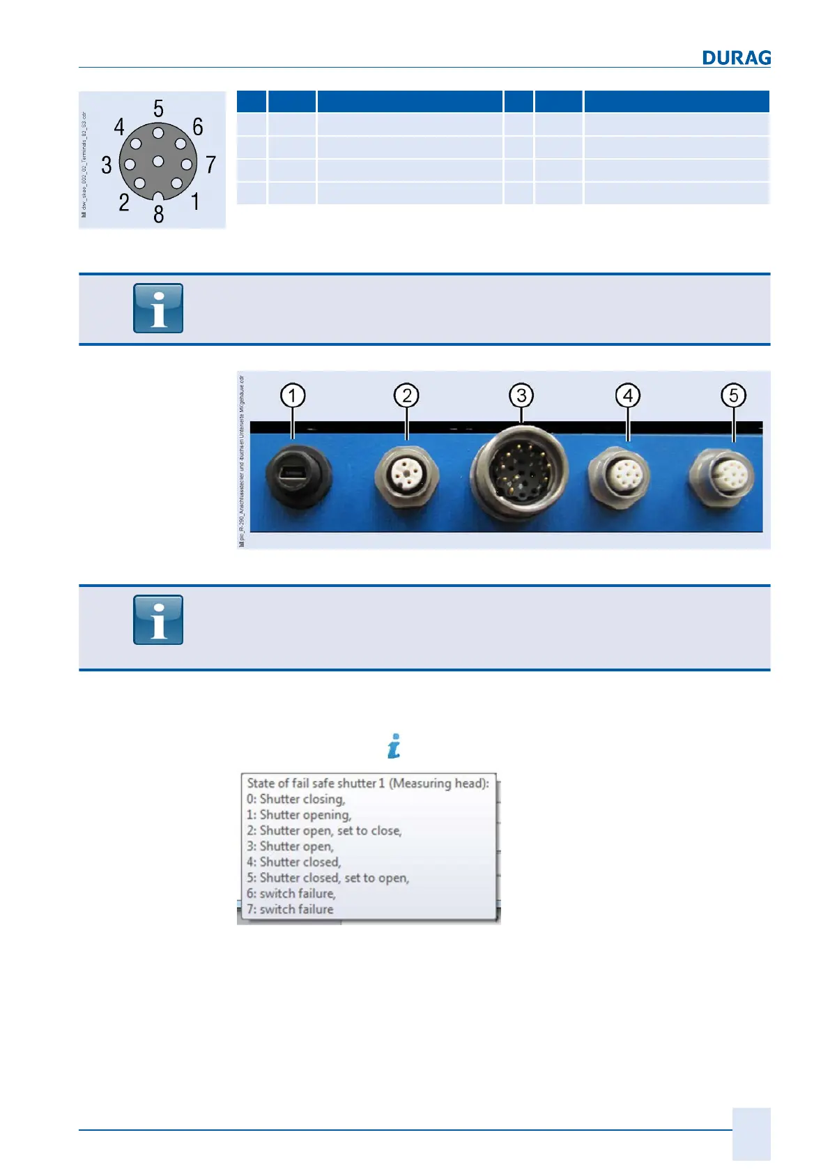
Fig. 7.18: Connection plugs and sockets on the underside of the housing
The assignment of the purge air monitoring and the fail-safe shutters is:
▶ Sensor 1 / shutter 1: -> measuring head -> connection 4 in Fig. 7.18
▶ Sensor 2 / shutter 2 -> reflector -> connection 5 in Fig. 7.18
The status of both fail-safe shutters can be interrogated here.
An explanation of the status codes can be displayed as Quick Info [} 196] (hover the
mouse cursor over the start of the line).
Fig. 7.19: Quick Info explanation of the shutter status
Activation of the fail-safe shutters includes a protective function to avoid damage if the
shutter is blocked.
If within 3 minutes the shutter has not completely opened or closed, it will automatical
ly be set by the system to "closed".
In addition the parameter "
fail-safe shutter 1 (or 2) blocked and deactivated"
is set by
the measuring head to "1".
Fig. 7.17: Pin assignment or
the purge air monitoring
plug
Fail-safe shutter
 Loading...