7 | Checking / setting parameters with D‑ESI 100
150
D-R 290
The following illustrations show the connection of temperature transmitter both with
and without their own power supply. 2
−wire transducers up max. 30 mA can be pow
ered directly by the D‑R 290 measuring head.
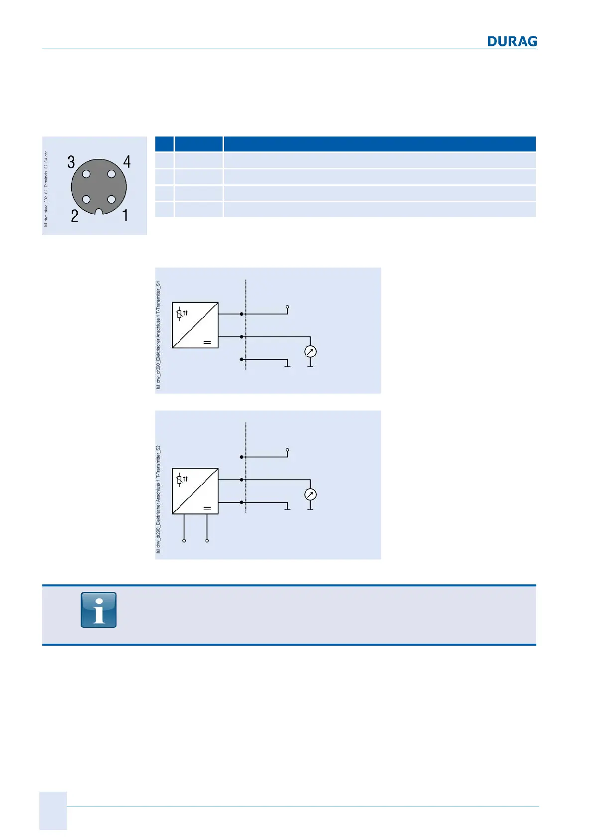
The connecting cable for the temperature transmitter is connected via a plug into the
socket in the measuring head.
Pin Colour Function
1 bn 24 VDC, max. 30 mA
2 wh Input 4..20 mA
3 bu n.b.
4 bk GND
Table 7.15: Pin assignment of the device socket for connection of the 4-20 mA temperature transmitter
The designations shown in
Fig. 7.24 for the device socket (1-4) match those for the
Fig. 7.25 and Fig. 7.26 .
D-R 290 TC inlet temperature (4..20 mA)
Transducer
4..20 mA
max. 20V / max. 30 mA
1
2
4
Fig. 7.25: Electrical connection of a 2-wire transducer (without its own power supply)
D-R 290 TC inlet temperature (4..20 mA)
Transducer
4..20 mA
max. 20V / max. 30 mA
1
2
4
Power supply
Fig. 7.26: Electrical connection of a 4-wire-transducer (with its own power supply)
The configuration of the temperature transmitter requires Service Engineer access
rights. The system is delivered from the factory correctly configured. If changes to the
configuration are necessary, please contact DURAG Service (for addresses see
DURAG GROUP company addresses.
Fig. 7.24: Pin assignment
connection
, temperature transmitter
 Loading...