7 | Checking / setting parameters with D‑ESI 100
D-R 290
143
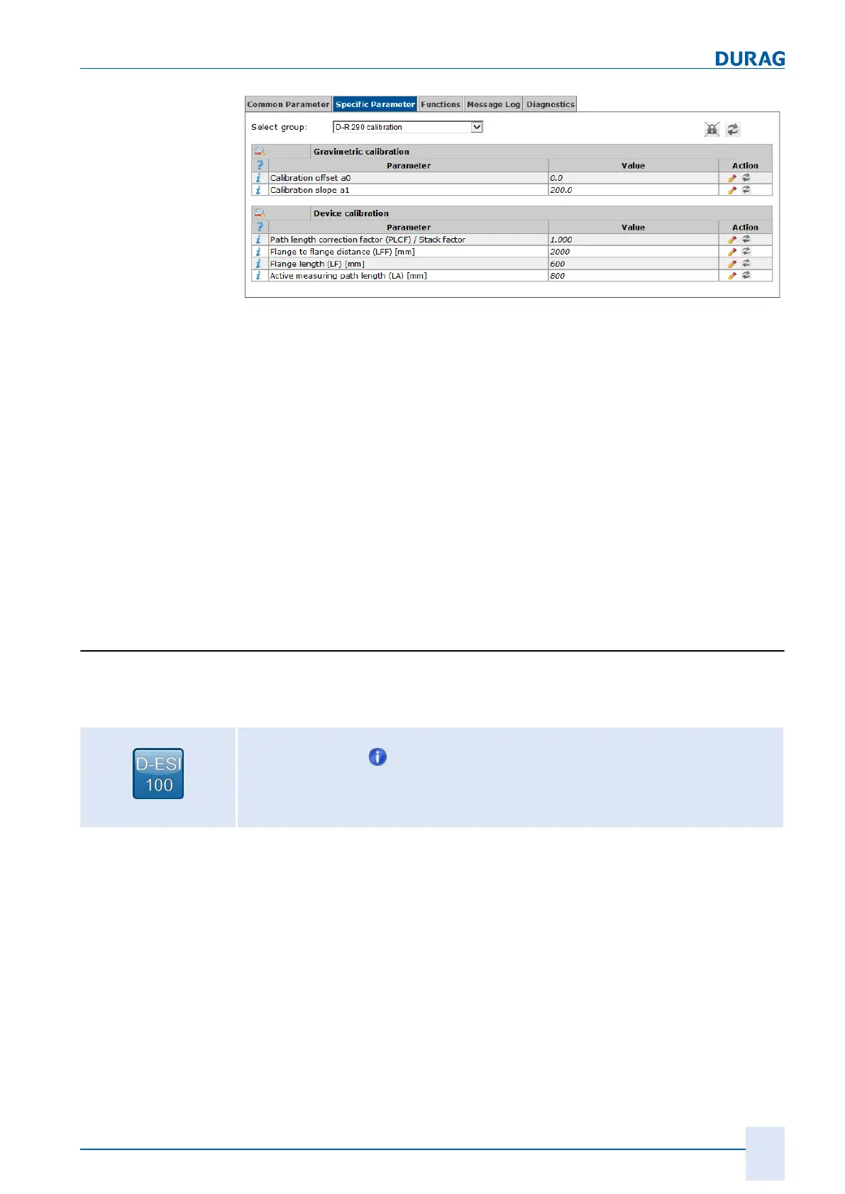
Fig. 7.15: Calibration
After
gravimetric calibration
of the D‑R 290 a calibration offset and calibration gradient
can be set here.
The relationship between the optical density and dust content, (values are determined
within the gravimetric calibration) is saved in the device by these calibration parame
ters. This allows the direct display of the dust concentration (see section
4.2.6 Optical
density (extinction) [}
48]
).
In addition the active measurement path length for calculation of the extinction coeffi
cient and the Koschmieder visual range can be saved (see also section
4.2.6 Optical
density (extinction) [}
48]
).
The values for the flange-flange distance (LFF) and the flange length (LF) can also be
saved for reference. If these values are input, the active measurement path length is
calculated automatically, using the formula LA = LFF – 2 × LF.
The stack correction factor can be input for an opacity evaluation according to US
EPA regulations (see section 4.2.5 Calculation of the opacity at the flue stack opening
[
} 46]).
Device status:
The device status shows various parameters which give information about the operat
ing status of the
D‑R 290.
These include for instance the inner temperatures, status of
the purge air monitoring and status of the fail-safe shutter.
Setting path:
Device (
D‑R 290 ) >
> Specific Parameters > D‑R 290 device status >
Calibration offset
Calibration gradient
Measuring path length
Flue stack
correction factor
7.7.7



 To Next Page