4
Installation and Set-Up
(continued)
Analog video output
DVI-D digital video output
Digital Audio Out 2 (Optical)
Digital Audio Out 1 (Coaxial)
Component Video 1 (YPbPr)
Component Video 2 (YPbPr)
S-Video 1
S-Video 2
Video 1 (Composite)
Video 2 (Composite)
Analog Pass-Thru
DVI
Digital Audio 1 (Coaxial)
Digital Audio 4 (Optical)
Digital Audio 2 (Coaxial)
Analog Audio (L/R)
iScan HD+
Video
Processor/
Scaler
DVD Player or other Component video
source with Digital Audio output
SDI*
Digital Audio 3 (Optical)
DVD Player or other SDI* video
source with Digital Audio output
Projector, HD-Ready TV,
Plasma display panel,
computer monitor,
or other SD/HD capable
display device
DVD Player or other Component video
source with Digital Audio output
DBS Receiver, Game Console or other
S-Video source with Digital Audio output
DVD Player or other
S-Video source
VCR or other
Composite video source
Laserdisc Player or other
Composite video source
HD-DBS Receiver, PC, or other
High Definition video source
HD-DBS Receiver, PC, or other
High Definition video source
AV Preamplifier/Processor or AV Receiver
Digital Audio Inputs
Analog
Audio
Inputs
or
* SDI Video Input Module required
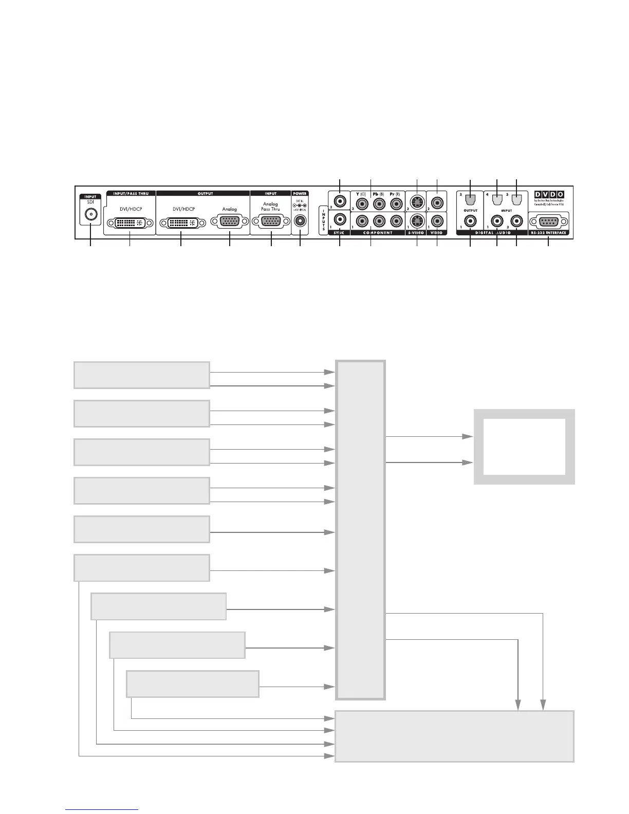
Signal Flow Diagram
The following diagram shows a typical way to use the iScan HD+
in a system. This figure depicts a system where the iScan HD+ is
used as the primary video switcher or “hub”. The iScan HD
+ is
usually placed between the display device and any video sources
and acts as the source switch for the display.
*
Component 2
(YPbPr or RGB)
Component 1
(YPbPr or RGB)
Power
Composite
Video 2
Composite
Video 1
Digital
Audio Out
2 (optical)
Digital
Audio Out
1 (coaxial)
Digital Audio
Inputs 4, 3
(optical)
Digital Audio
Inputs 1, 2
(coaxial)
Serial Port
S-Video 2
S-Video 1
Sync 2
Sync 1Analog
Output
Analog
Passthru
DVI OutputDVI InputSDI Input*
iScan Rear View Connections
The following figure shows the input and output connector com-
plement on the rear panel of the iScan HD
+. There are a total of
nine (9) Video inputs, two Video outputs, four (4) Digital Audio
inputs, and two Digital Audio outputs. Also shown are the DC
Power input and the RS-232 Serial Port.