5
Installation and Set-Up
(continued)
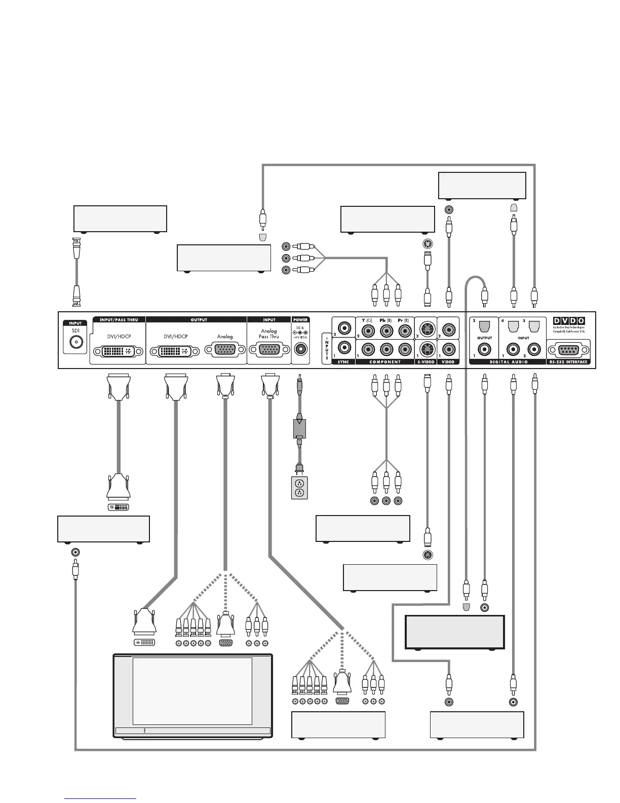
Typical System Configuration
The iScan HD+ is usually placed between the display device and
any video sources and acts as the source switch for the display.
Shown in this connection diagram are nine audio/video
sources, four of which have digital audio outputs along
with analog video outputs.
DVI-D
DVI-D
DVI-D
Progressively Scanned TV or Projector
Universal
Power Adaptor
AC Mains
(100-240 VAC
50/60 Hz)
Component
Video Cable
S-Video Cable
Composite Video Cable
S-Video Cable
Composite Video Cable
Digital Audio Cable (Optical)
Digital Audio Cable (Coaxial)
Digital Audio Cable (Coaxial)
Digital Audio Cable (Coaxial)
Component Video Source
(480i, 480p, 720p, or 1080i)
YPbPr
VCR or Other
S-Video Source
Component Video Source
(480i, 480p, 720p, or 1080i)
Set-Top Box or Other
DVI source
HD Satellite TV Tuner, PC, or
Progressive-Scan DVD Player
5x BNC
3x RCA
or
or
Video Game or Other
Composite Video Source
Set-Top Box or Other
S-Video Source
Video Game or Other
Composite Video Source
DVI-D
Audio/Video Preamplifier/
Processor or AV Receiver
Component
Video Cable
Digital Audio Cable (Optical)
Digital Audio Cable (Optical)
YPbPr
Digital Audio Cable (Optical)
HD Video
DVI-D or DVI-I Interface Cable
DVI-D or DVI-I
Interface Cable
HD Video
5x BNC
3x RCA
or
or
HD15 HD15
HD15
HD15
Rear View of
iScan HD+
*
BNC Cable
DVD Player or Other
SDI* source
* SDI Video Input Module required
Digital Audio Cable (Coaxial)