7.7.2 Physical interface
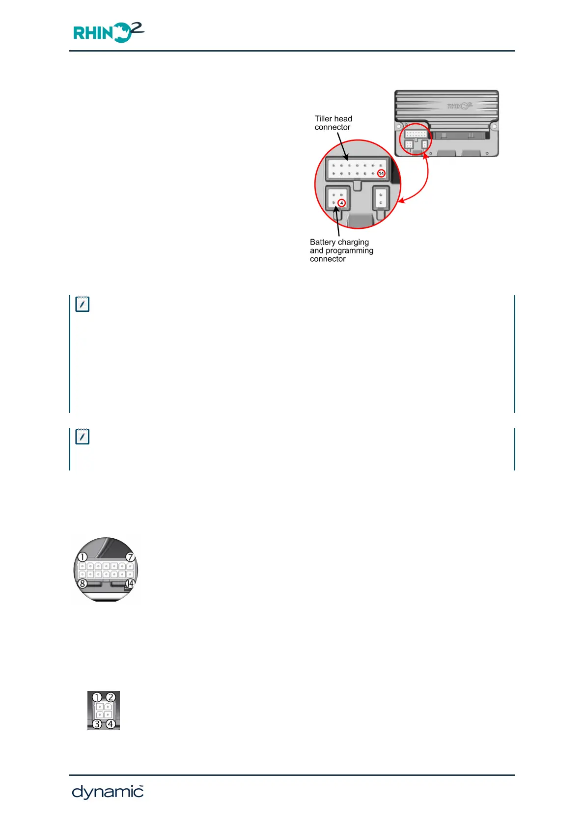
An external, third-party data logging device
can connect to one of the two single-wire
communication pins: pin 14 on the tiller head
connector (TH14) or pin 4 on the battery
charging and programming connector (BC4) —
see Figure 62 for pin location.
Note that the external data logging device can
connect to either pin — the information
transmitted on each pin is identical — but the
pin chosen must not be used for any other
circuit and must not be set as an inhibit.
Figure 62: Connectors and pin locations
Note
For RHINO2 modules with firmware version 1.24 and 1.28, to ensure reliable communication with an external
data logging device that employs a 3 V / 3.3 V UART, it is suggested that a resistor is fitted on the loom between
the single-wire communication pin (TH14 or BC4) and battery negative. As a guide, 1 KΩ is suggested, but this
needs to be verified through measuring the voltage levels on the connected device.
For later RHINO2 modules, with firmware version 1.35 or greater, do not fit an external resistor. The RHINO2
module is optimised for external data logging devices that employ a 3 V / 3.3 V UART, and a resistor fitted on
the loom with these later modules will prevent, if any, reliable communication.
Note
It is important that a common ground is established between the RHINO2 and the external data logging device.
This is achieved by connecting the external data logging device's ground to the RHINO2's battery negative.
7.7.2.1 Connecting to pin TH14
Connect a single wire to pin 14 of the tiller head connector via a 14-way, 2-
row, 4.2 mm pitch Molex, Mini-Fit Jr female connector housing
(manufacturer part no. 39-01-2145 — Dynamic part no. GCN0887). The
wire gauge should be a minimum of 0.5mm² (20AWG) and terminated with
a Molex, Mini-Fit female crimp terminal contact 18-24AWG (manufacturer
part no. 39-00-0039 — Dynamic part no. GCN0771).
In Wizard, set Pin 14 Function, which can be found under the Multi-function
Inputs Configuration group, to None.
7.7.2.2 Connecting to pin BC4
Connect a single wire to pin 4 of the battery charging and programming
connector via a 4-way, 2-row, 4.2 mm pitch Molex, Mini-Fit Jr female
connector housing (manufacturer part no. 39-01-3048 — Dynamic part no.
GCN0886). The wire gauge should be a minimum of 0.5 mm² (20AWG) and
terminated with a female Molex, Mini-Fit crimp terminal contact 18-24AWG
GBK51948 RHINO2
Installation Manual Issue 5
Diagnostics - Page 133
 Loading...


