5.9.13 Brake and Reversing Lights
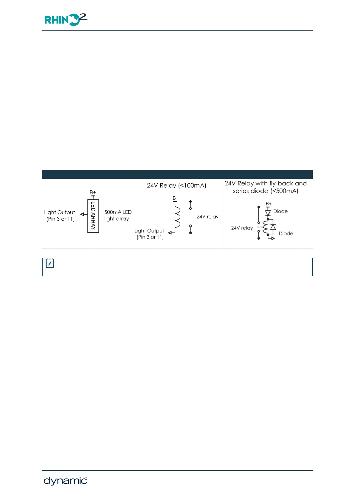
Pin 3 and Pin 11 on the tiller connector can be configured as either a brake light or
reversing light. Either light output may be connected to an LED array (500 mA) or relay-
driven incandescent or halogen bulb.
If an LED array is used, it must be a 24 V array and have its own internal current limiting
system. An LED array will also need to incorporate reverse polarity protection such as a
series diode.
Note: An LED array may exhibit a faint glow if not engaged.
The brake light will operate whenever the controller decelerates. The reversing light will
operate whenever the controller is driving in reverse.
LED Lighting Output Incandescent or Halogen bulb output
Note
Pins 3 and 11 can be set to one of Beeper, Brake Light, Reversing Light or Status.
GBK51948 RHINO2
Installation Manual Issue 5
Installation and testing - Page 47