AIR setups
Dynaudio Professional AIR reference manual – 2014-09-28 44
5.1 setup – digital – 192 kHz
5.1 setup – digital – 192 kHz
Master
L
System Ctrl.
Master
LS
Master
C
C + SubLF + RF
LS + RS
Slave
RS
Sub
Sub
Slave
R
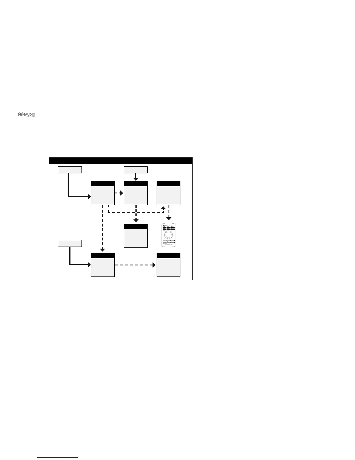
Fig. 24: This illustration shows how to connect a digital 192 kHz 5.1 setup.
Understanding and using this setup
►
Audio signals are represented by solid lines.
►
TC link signals are represented by dashed lines.
This is a 5.1 digital setup at 192 kHz with optional bass
management.
This setup requires…
►
three Master monitors with the optional Digital I/O
card installed,
►
two Slave monitors and
►
one subwoofer.
►
The left monitor is set as the System Controller by
setting the TC Link button on the rear panel to the
“out” position.
►
The left monitor receives the left and right front
channel signals.
►
The center monitor receives the center channel
and the subwoofer signal.
►
The left rear monitor receives the left surround and
right surround channel signals.
►
The subwoofer receives its signal via the TC LINK
RJ-45 connection from the center Master monitor.
►
A clock signal must be sent over the AES connec-
tion feeding the Center/LFE channels (or via BNC).
►
With no bass management, only the LFE signal is
fed to the Sub.
►
With bass management activated, low-frequency
information is extracted from the ve main chan-
nels below the set crossover frequency and fed to
the subwoofer, where it is summed with the LFE
channel.
►
The AIR Remote or a computer running the AIR
Control software (both optional) can be connected
to any available TC LINK Out connection.