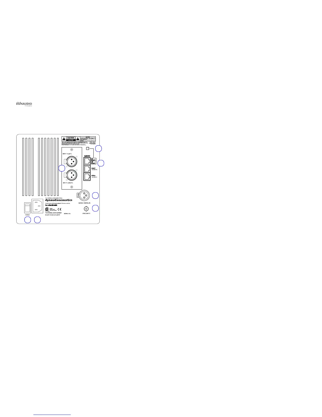
Rear panel controls and connections
Dynaudio Professional AIR reference manual – 2014-09-28 14
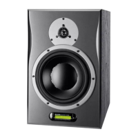
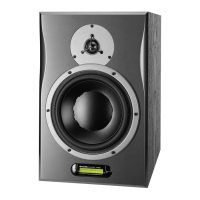
AIR Master unit with analog inputs – rear panel
1
6 7
5
3
4
2
Fig. 3: AIR Master unit with analog inputs – rear panel
1. System Controller/Slave switch
Out position: The monitor operates as a System
Controller. There can be only one System Control-
ler in a setup.
In position: The monitor operates as either a regu-
lar Master or a Slave unit.
2. RJ45 Link connections for downstream Slave units
3. Option slot with analog I/O card installed (optional)
4. AES/EBU digital Input
5. Word Clock BNC sync input
6. Power input – 100 to 240 V
7. Power On/Off switch
 Loading...