From lab to production,
providing a window into the process
-4-
www.dynisco.com
Rev: n/aP/N: n/a ECO: n/a
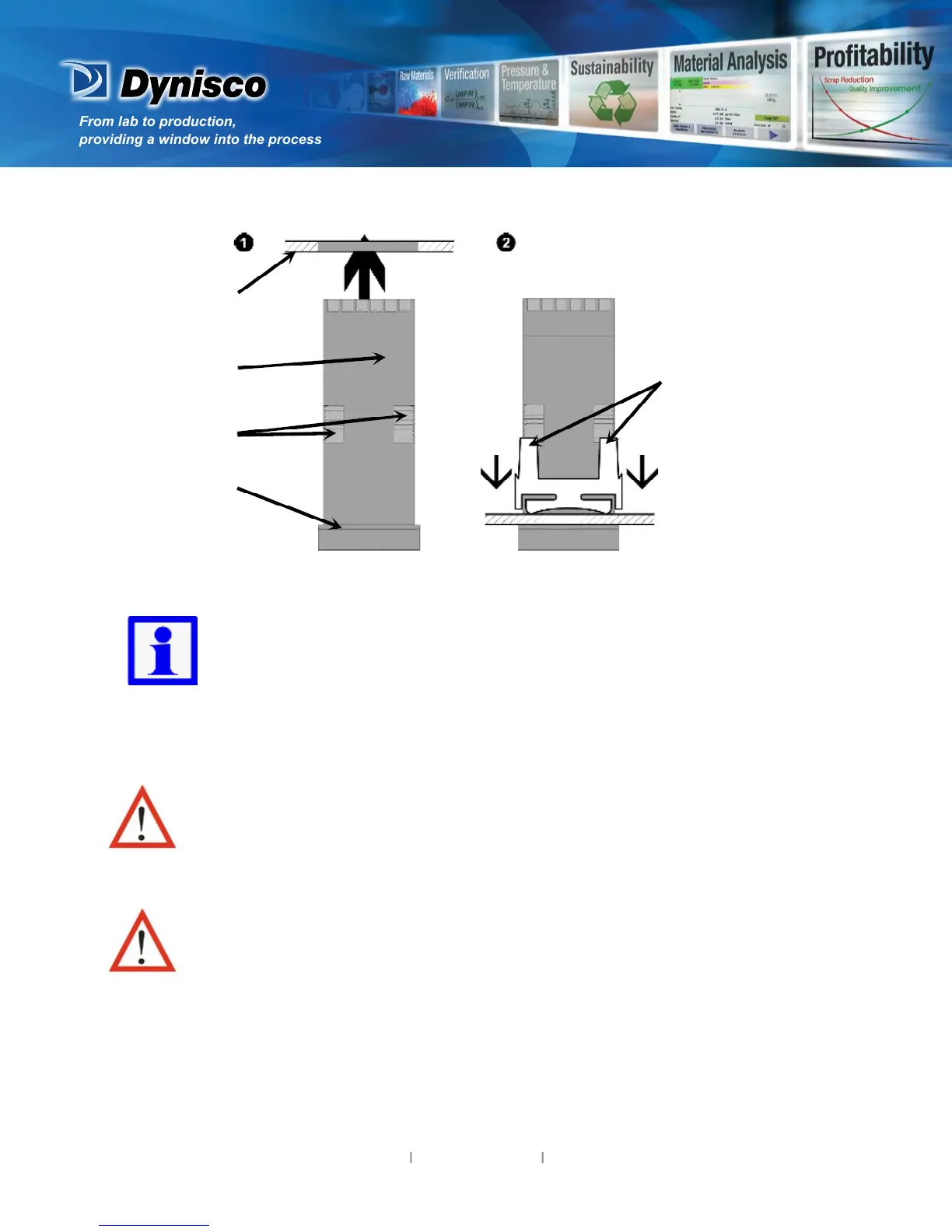
Mounng Panel
Instrument
Housing
Ratchets
Gasket
1. Insert instrument into
the panel cut-out.
2. Hold front bezel
rmly (without
pressing on display
area), and re-t
mounng clamp.
3. Push clamp forward,
using a tool if
necessary, unl
gasket is
compressed
and instrument held
rmly in posion.
NOTE: For an eecve IP66 seal against dust and moisture, ensure
gasket is well compressed against the panel, with the 4 tongues located
in the same ratchet slot.
Rear Terminal Wiring
All connecons to the device must be made through a spade format or similar
connecon, with connecon to the spade terminal touching both the insulaon and
conductor material. (Use a standard crimping tool). Connecons must be
mechanically secured so as to prevent any wiring becoming loose and coming in
contact with other wires or the instrument casing.
The above applies to any and all connecon to hazardous mains supply, either direct
or indirect (e.g. via a switch or relay).
USE COPPER CONDUCTORS (EXCEPT FOR T/C INPUT)
Use Screened Cable on Retransmission Opon 1
Single Strand wire gauge: Max 1.2mm (18SWG)