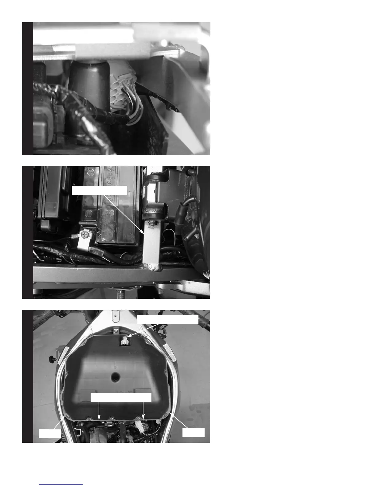
5. Route connectors from the
PCIII one at a time between
the frame and inner fender
(Fig. D).
6. Route the PCIII harness
under the frame crossover
(Fig. E). The battery may
need to be removed to allow
clearance for the connectors
and harness.
7. Lift the front of the fuel tank
up. Remove the air box. To
remove the air box loosen
the the two 3mm allen
screws at the rear of the
air box (Fig. F). Also
disconnect the hoses and
electrical connector as
shown in Fig. F.
Fig. DFig. E
Fig F
2004 Kawasaki ZX6RR - PCIII USB - 3i213-411 www.powercommander.com
Frame Crossover
3mm Allen Screws
Electrical Connector
Hose
Hose

 Loading...