Using Your D3
4-8 D3 Pilot’s Guide
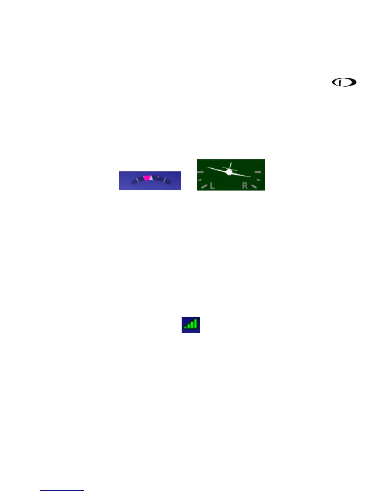
Turn Rate is displayed as a curved magenta bar just within the roll scale when the Turn Rate
display setting is set to “Magenta Bar”. The bar grows in the direction that the aircraft is currently
turning. The inner white markings on the turn rate indicator indicate a half standard-rate turn of
1.5 degree per second. The outer white markings indicate a standard rate turn of 3 degrees per
second. The turn rate arc example below depicts a half-standard rate turn to the left.
Figure 11 - Turn Rate Arc (left) / Airplane (right)
When the Turn Rate display setting is set to “Airplane”, turn rate is depicted as a more
conventional-style miniature airplane icon that behaves like the airplane in a classic turn
coordinator instrument. There are half-rate and standard rate markings. Like a conventional turn
coordinator, this depiction indicates turn rate, not bank angle. The airplane style depiction above
shows a half-standard turn to the right.
GPS Signal Strength is depicted in the upper left corner of the display. “Ext” is displayed alongside
the GPS Signal Strength indication when the external GPS antenna is connected.
Figure 12 - GPS Signal Strength