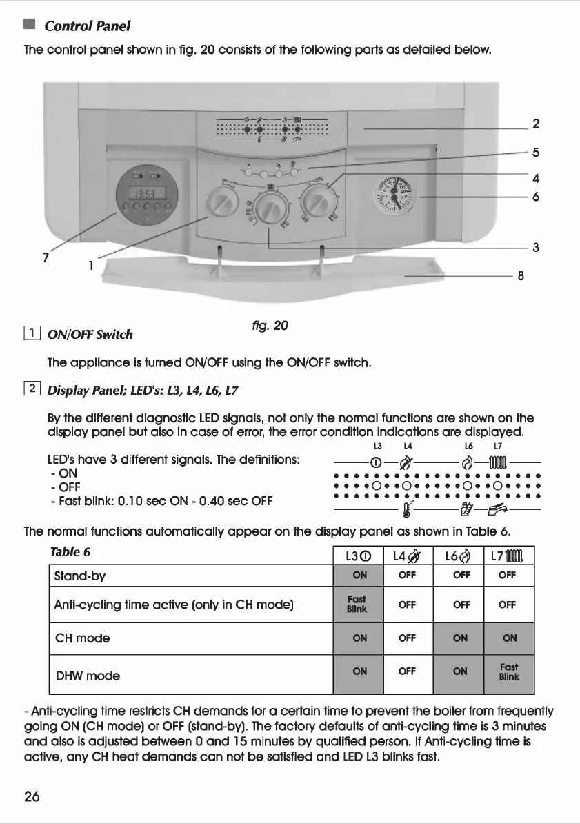
• Control Panel
The
control panel shown
in
fig. 20 consists
of
the following parts as detailed below.
- -
(JJ
-
cjl
-
<)
-
!11[
--
·.
+
·:::::·
::
+:
.....
:
--
-8-
't
-~~
--
ITJ
ON/OFF Switch
fig.
20
The
appliance
is
turned
ON/OFF
using the
ON/OFF
switch.
[]]
Display
Panel; LED's:
L3,
L4, L6,
L7
By
the different diagnostic
LED
signals, not only the normal functions are shown on the
display
panel
but also
in
case
of
error, the error condition indications are displayed.
LED's
have 3 different signals.
The
definitions:
-ON
-OFF
-
Fast
blink:
0.1
0 sec
ON
- 0.40 sec
OFF
L3 L4
L6 L7
--(f)-cJf--~-mm-
• • • • • • • • • • • • • • • • • • • • •
••••0••0•••••0••0••••
• • • • • • • • • • • • • • • • • • • • •
---1'
"
{1-~-
The
normal functions automatically
appear
on the display
panel
as
shown
in
Table
6.
Table 6
L3(f)
L4
c}f
L6~
L7illffi
Stand-by
ON
OFF OFF OFF
Anti-cycling time active (only
in
CH
mode)
Fast
OFF OFF OFF
Blink
CH
mode
ON
OFF
ON
ON
ON
OFF
ON
Fast
DHWmode
Blink
- Anti-cycling time restricts
CH
demands for a certain time to prevent the boiler from frequently
going
ON
(CH
mode) or
OFF
(stand-by).
The
factory defaults
of
anti-cycling time
is
3 minutes
and
also
is
adjusted between 0
and
15 minutes
by
qualified person.
If
Anti-cycling time
is
active,
any
CH
heat demands
can
not
be
satisfied
and
LED
L3
blinks fast.
26