090000964 - Telecamere IP e-Vision serie SMART - Quick Guide
21
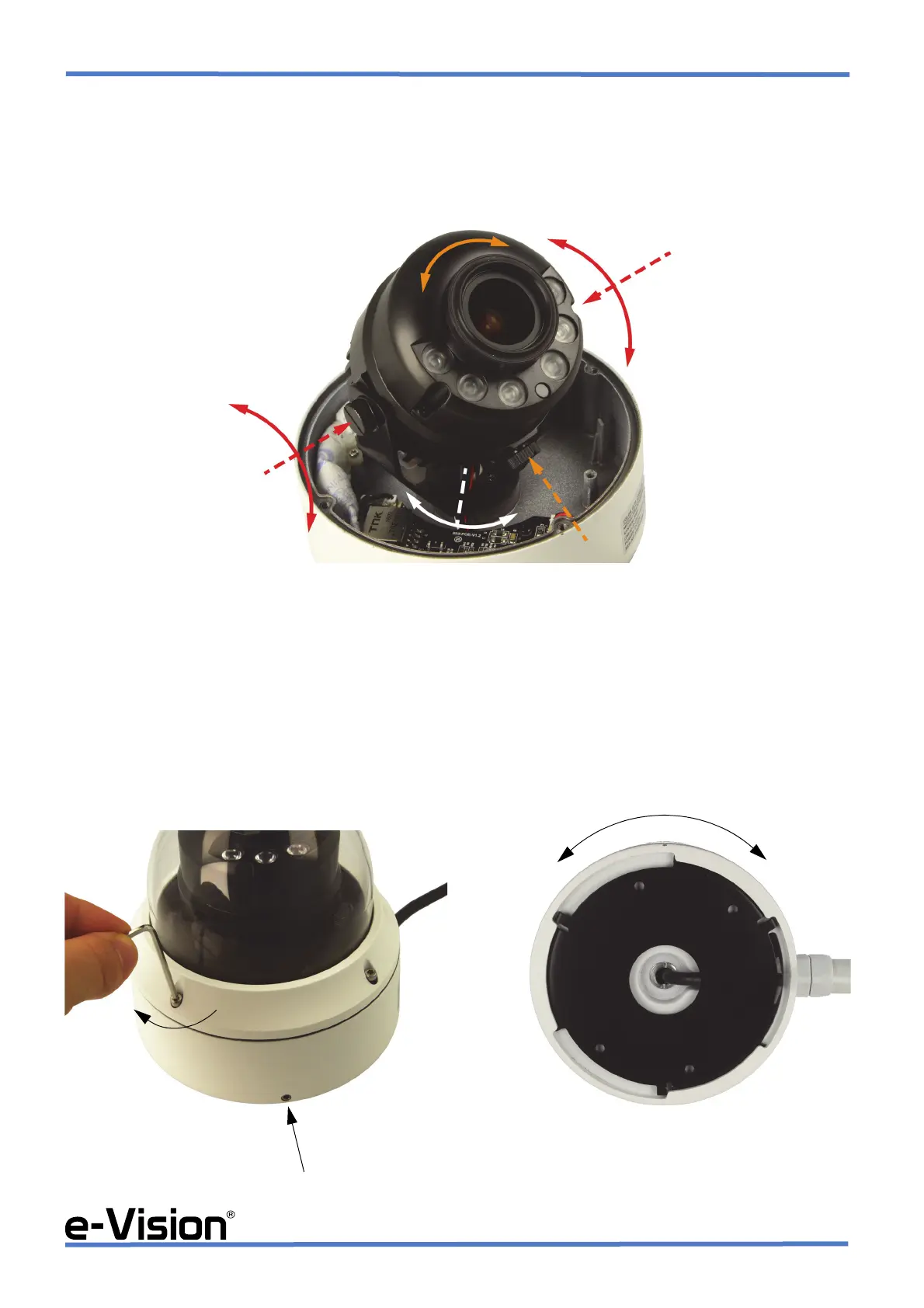
•STEP 4
Loosen the locking screws indicated by dotted arrows in the image below.
Adjust the three-axis motion of the camera by rotating the camera body as indicated by the curved arrows.
Tighten the locking screws to fix the camera in place.
•STEP 5
A : fix the camera in place and screw the dome again, removing any protective film and placing a Silica Gel packet inside
(See chapter 5.4 on page 24).
If you need to have the cable go out through the side hole, loosen the grub screw on the side with the provided hex key and
proceed with item B
B : remove the base by rotating it clockwise. Place the cable in its special path, then set the base in place again by rotating
it anticlockwise and by tightening the grub screw again.