EC5000
- 30 - - 31 -
Operation and inspection
3
EC5000
Installation and Wire Layout
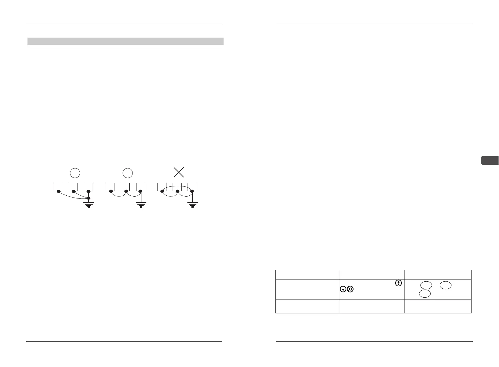
Best Fair Wrong
■ For safety and noise reduction, the grounding terminals of AC drive
should be well grounded.
■The grounding wire of AC drive can’t be grounded together with the
machines with heavy current load e.g. the electric welding machine and
high power motor, they should be grounded separately instead.
■ In order to prevent electric shock and fire, the external metal
grounding wires of electric equipment should be wide and short, and
connected to the special grounding terminals of the AC drive system.
■ If there is more than one AC motor speed controller connecting
with the ground, Please make sure that is does not form grounding loop,
shown as the following figures:
Grounding terminals of AC drive (EG)
3.1 Check and Test Before Operation
The following matters should be paid attention before the operation:
■Check if wire connection is correct. Confirm AC drive output permInal
U, V, W is not connected to POWER and the ground terminal E(G) is grounded
well.
■ Confirm there is no short circuit within every terminal and electricitied
naked part.
■Confirm all terminals connection and joints are tight and not loose
■Ensure that the motor isn't connected with loaded machine.
■Before turning the power on, ensure that all the switches are in the
disconnected state to guarantee that the AC drive won't start or operate
abnormally when the power is on.
■ The power supply can only be turned on after the upper cover is
installed.
■It is forbidden to operate the switch with wet hand.
■Display of the keypad panel (no indication of faults)
■The cooling fan installed in the AC drive should work normally.
3.2 Running Way
There are many running ways showed in “Chapter 4 CONTROL PANEL
AND OPERATION” and Chapter5 “FUNCTION DATA ILLUSTRATIO
N”.Choose the best operation way according to actual need and running
regulations. The common running ways are listed on figure 7-1
running way
key panel operation
Remote Control
Keyboard keys select
or panel adjustment
potentiometer
frequency setting
potentiometer or
simulated voltage current
running order
Press FWD or REV to start
and STOP to stop
Input joint terminal S1-
SC、terminal S2-SC