Do you have a question about the EACON EC6000 Series and is the answer not in the manual?
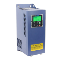
Welcome message and overview of the EC6000 series AC drive.
Information on dangerous usage and potential casualties or equipment damage.
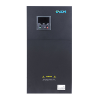
Details on understanding the AC drive model label and its components.
Explanation of the model naming convention and structure.
Breakdown of the serial number format and its meaning.
Table of product specifications including voltage and power ratings.
Details on standard functional specifications for the AC drive.
Explanation of individualized and advanced functional specifications.
Details on the standard input and output terminals and their functions.
Information on the LED and LCD display functionalities.
Details on copying parameters and locking keys to prevent mis-operation.
Overview of protection modes and list of optional accessories.
Recommendations for installation location, temperature, humidity, and vibration.
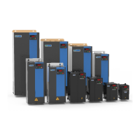
Dimensional data for AC drive structure A, including W, W1, H, H1, D, D1.
Dimensional data for AC drive structure B, including W, W1, H, H1, D, D1.
Description of main circuit terminals for power input and motor output.
Details on external power supply and PLC input terminals.
Description of LED and LCD operation panels, including their features.
Explanation of the indicators on the operation panel and their meanings.
Details on analog input/output, digital output, and relay output terminals.
Information on the RS485 communication interface.
Explanation of the function of each key on the LED operation panel.
Details causes and solutions for inverter protection, overcurrent, overvoltage, and control power faults.
Covers faults like motor overload, power phase loss, module overheat, communication, and encoder errors.
Parameters for drive selection, motor control, and frequency sources.
Detailed settings for motor characteristics like power, voltage, current, and speed.
Configuration parameters for vector control modes and speed loop settings.
Configuration of V/F curves, frequency, and voltage settings.
Configuration of digital and terminal functions for input signals.
Settings for terminal selection, filter times, and command modes.
Parameters for terminal protection, frequency control, and output functions.
Settings for analog input and output terminals, including signal selection and filtering.
Parameters for controlling start, stop, DC braking, and ramp functions.
Settings related to system configuration, password, and operation modes.
Parameters for display, copy, and auxiliary functions.
Configuration for fault detection, protection modes, and auto-reset functions.
Settings for PID control loops, including feedback and gain settings.
Settings for internal PLC functions, run modes, and timing parameters.
Parameters for user-defined functions and macro selection.
Configuration for torque control modes, frequency, and time settings.
Parameters for multi-pump control, increments, and industry frequency settings.
Parameters for monitoring drive status like frequency, voltage, current, and temperature.
Introduction to ModBus RTU protocol, master/slave control, and RS485 interface usage.
Description of the data frame format, including byte composition and timing.
Details on the Modbus RTU message structure, including start, address, order code, data, and verification.
Explanation of order codes for reading and writing parameters, with examples.
Information on responses from sub machines, both normal and abnormal.
Methods for verifying communication frame integrity, including odd-even and CRC checks.
Rules for defining communication data addresses for controlling AC drives.
Instructions for control order functions, including running state and communication commands.
List of fault codes and their corresponding descriptions for AC drives.
Diagram showing connections for main power input, reactor, and motor output.
Diagram illustrating connections for digital inputs, analog inputs/outputs, and communication.
Important notes and precautions regarding wiring, including terminal functions and shielding.
Details for filling out the warranty card, including user and distributor information.
| Cooling Method | Forced air cooling |
|---|---|
| Enclosure Rating | IP20 |
| Input Voltage | 380V/220V AC, ±15%, 50/60Hz |
| Overload Capacity | 150% of rated current for 60 seconds |
| Protection Features | Overcurrent, overvoltage, undervoltage, overload, overtemperature, phase loss, short circuit protection |
| Communication Interfaces | RS485 |
| Ambient Humidity | 5% to 95% RH (non-condensing) |
| Braking | Built-in braking unit (for some models), external braking resistor can be connected |