Do you have a question about the EACON EC5000 Series and is the answer not in the manual?
Guidelines for safe handling and movement of the AC drive.
Recommendations for proper storage conditions to maintain product integrity.
Factors to consider when selecting an AC drive for specific applications.
Key parameters and settings for AC drive operation and configuration.
Specifies the recommended ambient conditions for AC drive installation.
Details on mounting orientation, ventilation, and installation requirements.
Provides physical dimensions and mounting hole information for AC drives.
Specific installation dimensions for 200V AC drive models.
Specific installation dimensions for 400V AC drive models.
Comprehensive guide for connecting power and control wiring to the AC drive.
Fundamental principles and diagrams for AC drive wiring connections.
Detailed mapping of control terminal symbols to their functions and names.
Illustrates the overall wiring schematic for the AC drive system.
Specific instructions for connecting the main power loop terminals.
Essential pre-operation checks and safety procedures for the AC drive.
Procedure for testing the AC drive's functionality after installation.
Overview of the LED keypad's layout and how to operate it.
Details the visual elements and indicators on the LED keypad.
Step-by-step guide for using the LED keypad for operation and settings.
Overview of the LCD keypad's features and operation procedures.
Guide for setting functional parameters via the keypad interface.
Comprehensive list of all functional parameters with their settings and addresses.
In-depth explanations of specific functional parameters and their effects.
Explains how acceleration and deceleration times are defined and set.
Configuration of different operating modes for the AC drive.
Explains the functions assigned to input terminals S1 through S8.
Configuration of terminal functions based on different wiring and control modes.
Configuration of timer functions for various operational delays.
Setting the UP/DOWN order function for frequency control.
Explains the functions assigned to output terminals Y1 through Y4.
Illustrative examples of parameter settings and their effects.
Configuration for the AC drive's instant stop behavior.
Settings for search current and minimum baseblock time.
Settings for DC braking time and motor rotation moment compensation.
Procedures for testing motor rotation moment of force and its standards.
Settings for SPO delay, power selection, and PID control.
Configuration options for PID control mode and feedback adjustments.
Enabling and configuring energy saving control modes and voltage settings.
Setting the communication address and baud rate for Modbus networks.
Configuring Modbus parity, run time tests, and CE stop methods.
Settings for L/R selection, enter key, variable selection, and display.
Configuration for low-speed, zero-speed, motor tuning, and electrical leakage.
Settings for step length, wire selection, and fault history logging.
Defines the structure of data transmission for Modbus communication.
Specifies the format of data frames for ASCII and RTU modes.
Explains how to assign communication addresses for Modbus devices.
Details Modbus function codes and data character formats for register operations.
Information on Modbus commands for data writing, loop testing, and check values.
Maps parameter word addresses to their functions and descriptions for AC drives.
Protective actions taken by the AC drive upon detecting a fault.
Lists fault codes, their descriptions, and troubleshooting details.
Lists alarm codes, their descriptions, and troubleshooting illustrations.
Procedure for resetting alarms and clearing fault statuses.
Discusses common causes of AC drive malfunctions and their solutions.
Explains harmonic generation and mitigation measures for AC drives.
Routine checks to perform on the AC drive during daily operation.
Scheduled inspections to ensure the AC drive's long-term reliability.
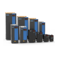
Technical specifications and rating schedules for EC5000 AC drive models.
Detailed technical performance indexes and specifications for the AC drive.
Information on optional accessories like digital keypads and external components.
Dimensional drawings for optional base installation accessories.
Selection guide for appropriate braking resistors based on AC drive model.
Wiring and parameter settings for using an external potentiometer as frequency source.
Configuration for two-wire control using terminals S1, S2, SC for operation.
Configuration for three-wire control using terminals S1, S2, S3, SC for operation.
Methods for setting frequency and controlling start/stop via the panel.
Terms and conditions of the product warranty.
| Storage Temperature | -20°C to +60°C |
|---|---|
| Cooling Method | Forced air cooling |
| Enclosure Rating | IP20 |
| Protection | Overcurrent, Overvoltage, Undervoltage, Short Circuit, Phase Loss |
| Communication | RS485 Modbus RTU |
| Operating Temperature | -10°C to +45°C |
| Humidity | ≤90%RH, non-condensing |