EC5000
- 68 - - 69 -
Description of Functional Parameter
5
EC5000
Description of Functional Parameter
Notice!
1. Keep the given value when T1,T3 is 100ms or longer.
2. Don’t keep the given value when T2 is smaller than 100ms.
OFF
OFF
ON
ON
OFF
Combined signal input
Selected time of accelerating
and reducing speed
14(RT2) 13(RT1)
A18 1 accelerate,A19 1 decelerate speed
A20 2 accelerate,A21 2 decelerate speed
A22 3 accelerare,A23 3 decelerate speed
A24 4 accelerate,A25 4 decelerate speed
ON
OFF
ON
Mumultifunction joint output time (Y1-4: Set 11)
Mumultifunction joint input time (S2-8: Set 22)
ON
ON
B16 B17 B16
B17
ON
ON
■ Set 22:timer function
The timer input is on when timer ON is longer than delay timer(B12)ON.
The timer output is OFF when timer OFF is longer than delay timer(B13)
OFF.
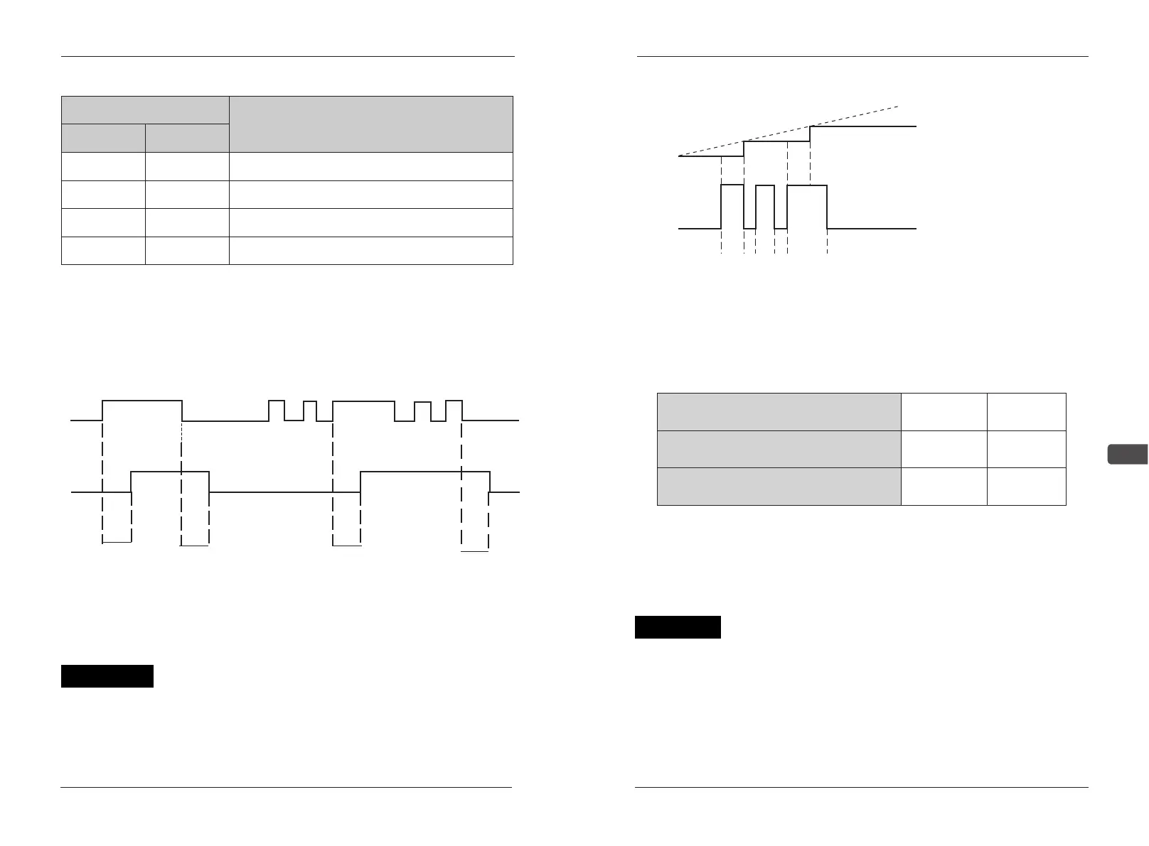
Setting 24:given simulate value sampling and keep
Simulate Fre. order is sampling when input terminal is “ON” is 100ms or
longer. When input terminal is “OFF”,the simulate Fre.value is kept.
■Set 27:UP/DOWN order(set:B07=27)
Only input the effective order, the AC drive acclerate/retard when input
UP/DOWN order to control circuit terminal S7 and S8 without changing
Frequency order. This makes AC drive runs at anticipated speed. When
UP/DOWN order is appointed by B07, all the function set by data B06 is invalid,
and terminal S7 changes to input terminal of UP, S8 changes to be DOWN.
The following figure shows the times sheet when input UP/DOWN
order
U=UP(accelerate status) D=DOWN(decelerate status) H=HOLD(keep)
U1=UP status(keep stable on up limit value) D1=DOWN status(keep stable
on up limit value)
■ Set Frequency up limit value when selecting UP/DOWN order, leave
alone Frequency order value.
■ The low limit can be from control terminal FV, FI simulate order, the
bigger one of AC drive order low limit.
■When input right(opposite)running order, AC drive start from low
Analog Input
Fref
100ms
t1 t2 t3
100ms
Control circuit terminal S7(UP order)
Control circuit terminal S8(DOWN order)
Running status
acclerate
decelarate
ON
OFF
OFF
ON
Notice!