EC5000
- 32 - - 33 -
Operation Keypad Panel
4
EC5000
Operation and inspection
Check whether the acceleration / deceleration are steady.
If there is no abnormality, perform the test run with frequency increased. If
no abnormality happens in the test run above, the formal operation can be
started.
If there is any abnormal phenomena occured, stop AC drive immediately.
Consult “ fault diagnosis” to find the problem. When AC drive stops,
terminal L1/R1, L2/S, L3/T is still with power if main circuit is not
switched off. Any touch onto terminal U, V, W will be shocked. Besides,
wave filter capacitor is still full of charging voltage and need certain period
of time to discharge, if main circuit power is off. Touch inner AC drive circuit
only after power and the DC circuit voltage tested by DC circuit voltage
meter is below safety voltage.
Notice!
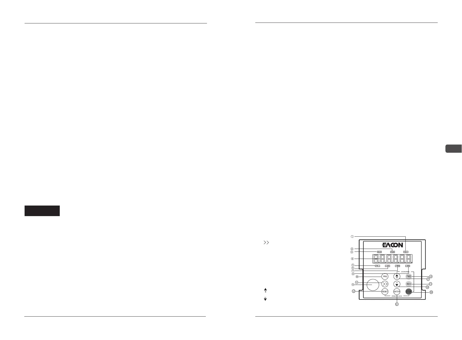
4.1 LED Keyboard Panel Appearance and
Operation Process
8 segment digital tube LED operation panel by six and seven leds, it can
display the running condition of AC drives, running direction, alarm, forecasting
warning information, panel/remote instruction, monitoring data, I/O status, the
parameters of the function of data set, etc.
The panel is detachable and isolated from the input potentiometer. The
panel is allowed to be removed during operation, but it is not recommended to
do so when running in relation to the panel, such as panel control
running/stopping and setting the frequency.
4.1.1Appearance of the Keypad Panel of Nixie
Tube
①REV This LED indicator light will be on when the motor is in positive rotation
②FWD This LED indicator light will be on when the motor is in reverse rotation
③RUN This LED indicator light will be on when the motor is running
④6-bit LED nixietubes display
⑤FAL This LED indicator light will be on when the frequency converter has faults
⑥LOC This LED indicator light will be on when controlled by the Panel
⑦REM This LED indicator light will be on when controlled by the control mode set by A03
⑧JOG This LED indicator light will be on when inching condition
⑨Knob of encoder
⑩PRG Enter set parameters
⑪ Move the position on the display
⑫RESET Abnormal reset; Exit after setting
⑬ENTER Parameters validation
⑭FWD Motor reverse rotation key
⑮REV Motor positive rotation key
⑯STOP Motor stop
⑰ Add value or move up parameters
⑱ Reduce value or move down parameters
3.3 Test Run
If no abnormality is detected after the inspection and preparation before the
operation according to 3-1, the test run can be performed. When the products
leave the factory, they are set to work in the external terminal operation mode,
which can be switched to manipulator operation mode via the key combination
of
1. After the power supply is on, confirm that the LED displays the frequency
0.00Hz.
2. Use the key to set low frequency around 5Hza
3.Press or to start and to low down and stop
4.Check the following before running:
Check whether the rotation of motor is correct.
Check whether the rotation of motor is steady (without abnormal noise or
vibration).