+
1
+
2
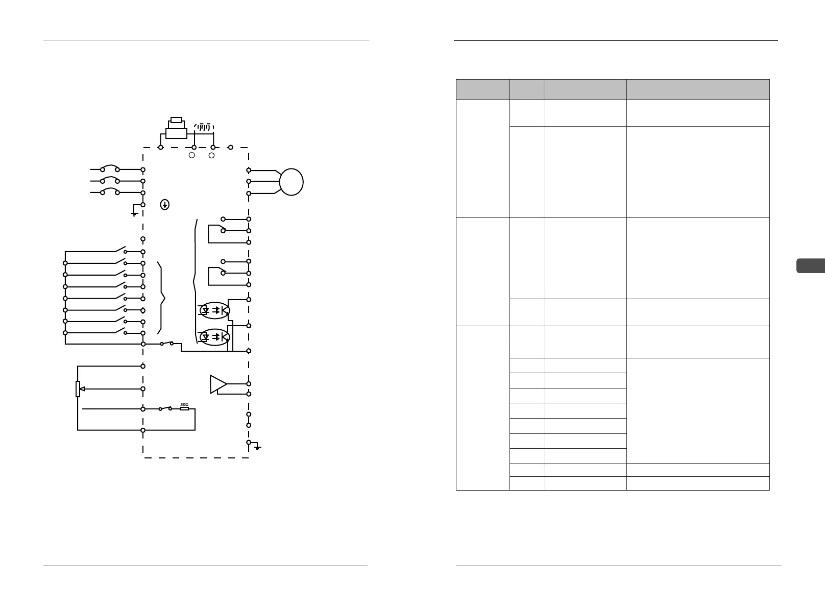
Basic Wiring Diagram 3
EC518D5G0022P43B~EC50560G0630P43B
EC5000
Output of multi-function analog quantity
-
R
S
T
PR
R / L1
U / T1
V /
T2
W /
T3
Y1A
AC250V/2.5A
DC24V/5A
AC250V/2.5A
48VDC/50mA
48VDC/50mA
0-10VDC/5mA
DC24V/5A
Y1B
Y1C
Y2A
Y2B
Y2C
Y4
YC
FMA
FC
DA
DB
EG
Y3
S / L2
T
/ L3
EG
S2
S3
S4
S5
S6
S7
S8
SC
FS(+12V)
FV
FI
FC
5K
SP(+24V)
S1(FWD)
SW1-2
SW1-1
Default settings
0/4-20mA
M
3~
DBU
DB
0-10V
Multi-speed Instruction 1
Multi-speed Instruction 2
Multi-speed Instruction 3
Inching instruction
Brake resistor
Brake unit (optional component)
DC Reactor (Optional component)
Short Circuit Plate (Default Setting)
Non-fuse breaker
Positive Rotation Run/Stop
Reverse Rotation Run/Stop
External Failure
Reset
Common terminal for
analog signals
Rs485 Communication data interface
The default setting is the
indication of the completion
of the preparation work of
AC motor driver
The default setting is consistent frequency
The default setting is the indication of running
The default setting is the indication of failure
Input of multi-function connection contact
Output of multi-function connection contact
power supply for frequency setting
+12V/20mA
Main analog quantity instruction
0-10V(4.7K)
Input of auxiliary
analog instrucion
Input of analog quantity
- 20 - - 21 -
Installation and Wire Layout
2
EC5000
Installation and Wire Layout
Note:
1.SW1:Input signal selection switch
V: Voltage 0-10 V I: Current 0-20mA
2.FV:B14=0, voltage input, SW1 to V (factory default)
3.FI: ①B14=1, B15=1, current input, SW1 to 1
②PID open feedback signal terminal, used in combination with SW1.
2.4.2 Control Terminal Connections
1. Frequency set by an external
analog input voltage command
Value
①0~10V DC/0~100%.
②antiaction:+10v~0V DC/0~
100%.
2. Input PID target control signal,
input impedance:20kΩ
Simulate
value
input
FS
FV
potentiometer
power
Voltage input setting
potentiometer power(+10VDC)
for setting frequency(1~10kΩ)
Sort Function
symbol
Terminal name
S2
Public input
terminal
Multifunction input2
S3
Multifunction input3
S4
Multifunction input4
S5
Multifunction input5
S6
Multifunction input6
Multifunction input7
S8
Multifunction input8
SP
+24V power
SC
Public terminal for signal input
Joint input
FC
Simulated public
terminal
S1
Positive
rotation/stop
Public terminal of simulated
input signal.
Terminal S1-SC: ON: Positive
rotation run OFF:low down
and stop
Simulate
value
input
FI
Current input
1. Frequency set by an external
analog input current / voltage
command value
①4~20mA DC/0~100%.(Set Sw1
is I)②0~10V DC/0~100%.
(Set Sw1 is V)
2. Input PID feedback control
singal, input impedance:250Ω
Max.output current :500mA
Terminal S2~S8 is functional for
motor free rotation, outside alarm,
alarm resume,multi-pace
frequencysignal. For more detail,
please check terminal function
Setting (S2~S8)(B01~B07)
S7