EC5000
Installation and Wire Layout
EC5000
Installation and Wire Layout
Sort Function
symbol
Terminal name
Simulate
value
FMA
Simulate monitor
(FC public terminal)
Output monitor signal of simulated
voltage 0~+10VDC
Choose one of the following
choices as the monitoring target:
0.output frequency(10V/max
frequency A10)
1.output current flow(10V AC drives
rated current)
2.power output(10V AC drive rated
current)
3.DC voltage10V/400V(200V
grade)800V(400V grade)
Joint
output
AC drives output minitor signal by
transitor OC, signals are
"RUNNING, FREQUENCY
ARRIVAL, OVERLOAD FORCAST,
ETC…There is 4 output singals
altogether. Please check terminal
function setting.
Y1/Y2
A/B/C
Y3Y4
Optional signal
output relay
Y3,Y4 Transitor OC
output Y3、Y4
communic
-ation
DA
DB
RS485 communic
ation input/output
RS485 communication input/
output terminal connecting
max.31 AC drives
■The connection with analog signal is especially easy to be influenced by
the interference of external noise, thus the wire should be as short as possible
(less than 20m), and shielding wire should be used. The outer wire mesh of the
shielding wire should be basically grounded, but if the inducing noise is very
loud, it is better to connect it to the FC terminal.
■ For the need of using contact in this circuit, the double-fork contact
which can process weak signals should be used. Besides, the terminal FC
should not adopt contact control.
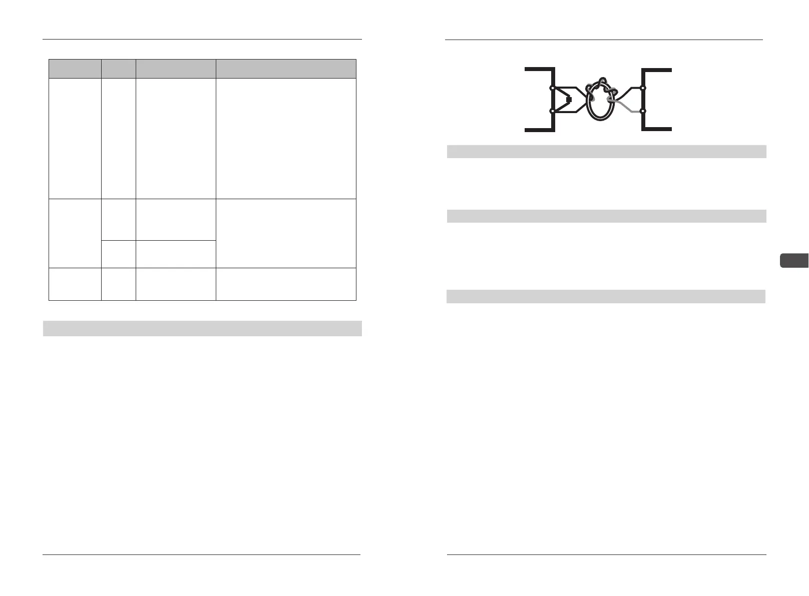
■ While connecting with the external analog signal follower, sometimes
the interference caused by the analog signal follower or the AC drive will
lead to misoperation, in such conditions, the capacitor and the magnetic core of
ferrite may be connected to the external analog follower, as shown below:
Analog input terminals (FS, FV, FI, FC)
- 22 - - 23 -
FV/FI
FC
C
Go through in-phase and encirle 3 loops or above
Ferrite magnetic ring
Input terminals of contact (S1~S8)
■ While controlling the input of contacts, in order to prevent bad contact,
the contacts that have high reliability for the contact with weak signals should
be used.
Output terminals of transistor(Y3, Y4 )
■The polarity of the external power supply should be correctly connected.
■ While connecting the control relay, the surge absorber should be
connected with the two ends of field coil. Please ensure that the polarity is
correctly connected.
■It's best to use the shielding wires as control wires, the isolation network
divested segment before the terminals should not be exposed.
■The wires of control terminals should keep away from the wires of the
main loop, or misoperation may be caused due to noise interference. If an
intersection is needed, make them intersect with a right angle.
■Generally the control wires don't have good insulation. If the insulation
layer is broken due to some reason, high voltage may enter the control circuit
(control panel), leading to circuit damage, equipment accidents or personal
Danger .
■ The control wires in the AC drive should be fixed properly to prevent
them from the direct contact with the charge-carrying part of the main circuit
(e.g. the terminal strips of the main circuit).
2
Input terminals of contact (S1~S8)
Output terminals of transistor (Y3,Y4)
Others