Appendix
EC5000
- 132 - - 133 -
9
Appendix
EC5000
Notice!
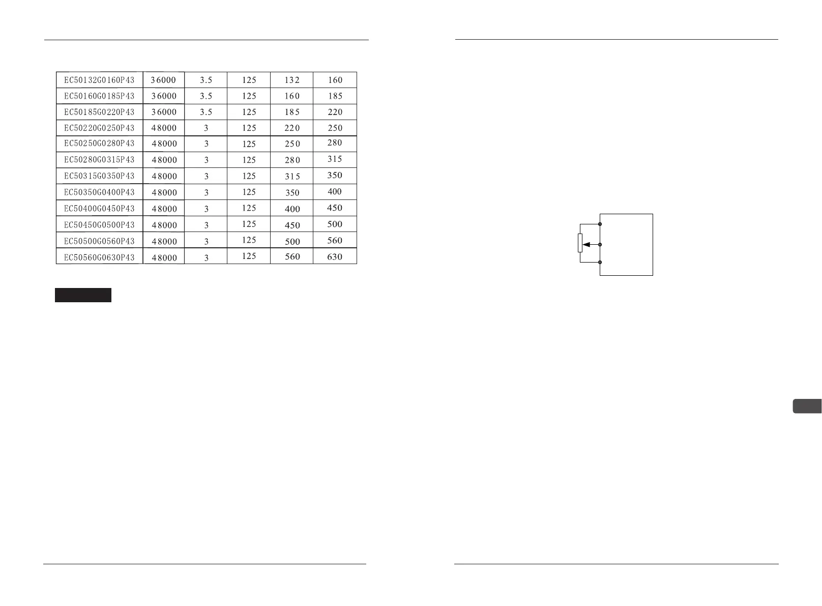
1.To implement fast braking, AC drives of specs 400V grade,≥
18.5KW and higher need to install a braking unit.
2.Choose the resistance and operation frequencies according to our
factory setting.
3.If braking resistors and braking IGBTs are not used our company
supply, then the AC drive or other devices damage, we will be of none
responsibility.
4.Please take environment safety especially flammability into
consideration during the installation of braking resistors.
5.If you want to change the resistance and power, please contact
local agents.
6.You shall order separately if you need braking resistors and
braking modules. Please contact local agents for details.
Appendix C-1the given frequency and operation panel of the
external potentiometer
1.The wiring diagram(1-1) of the external potentiometer terminals
A、B、C,usually choose 5-10K potentiometer, we can adjust terminal C
to judge the potentiometer.
Use the resistance of the multimeter to measure any two terminals
A、B、C,the biggest resistance is terminal A、B,the left one is the
terminal C which can judge the potentiometer.
2. Parameter setting: Choose the operation mode A03=2, the max
frequency A11 (the corresponding frequency of 10V)
Appendix C-2 Two wire form: Use S1,S2,SC to compose the
forward, stop, reverse. As shown 1-2
1. Choose terminals S1, S2
2. Parameter setting:
(1). The given frequency of external potentiometer and the external
terminals at the start
Choose the operation mode A03=3, the max frequency A11 (the
corresponding frequency of 10V),B01=0
(2) The given frequency of the panel and the external terminals at the
start
LED panel
When F12=0,the frequency is setted by A27,B01=0, choose the
operation mode A03=1;
When F12=1,the frequency is setted by panel potentiometer,B01=0,
choose the operation mode A03=1;
LCD panel
FS
FC
FV analogue
input
A
B
C
1-1