Appendix
EC5000
- 134 - - 135 -
9
Appendix
EC5000
The frequency is setted by A27,B01=0, choose the operation mode
A03=1.
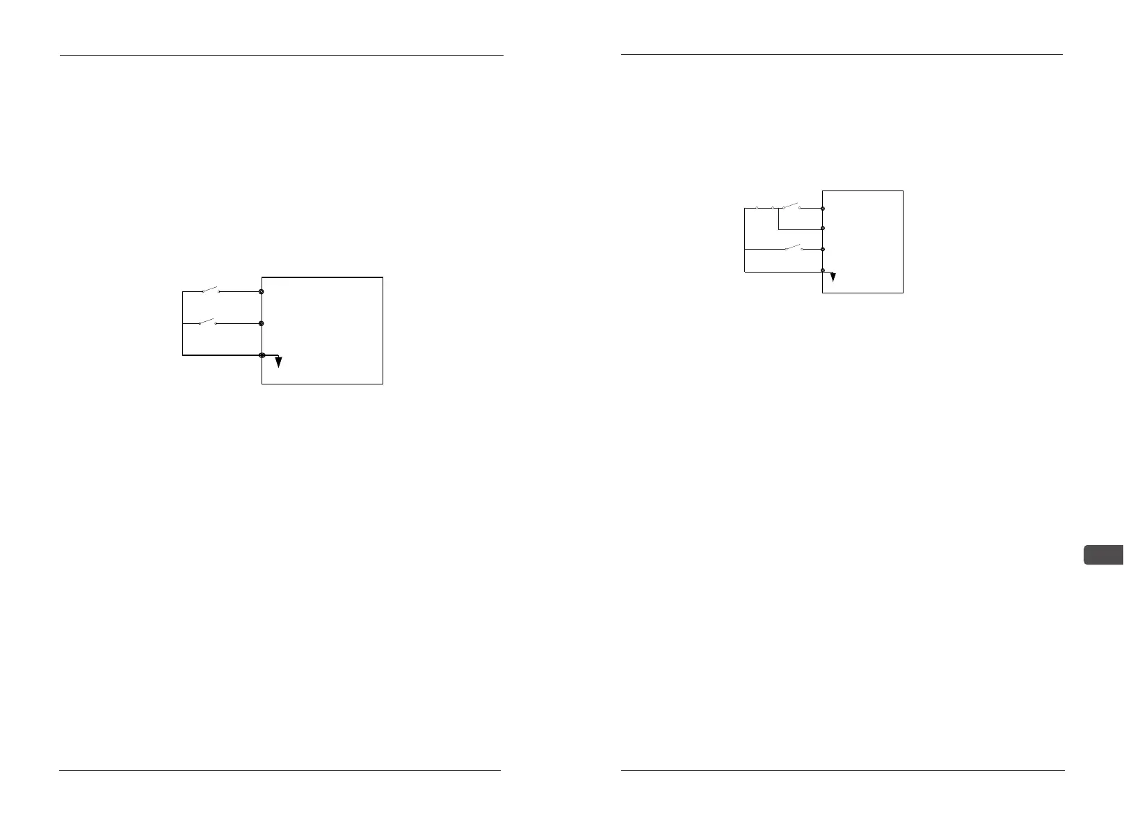
(3) Action description
When the switch A close,the inverter forwards;when it is opened,the
inverter stops.
When the switch B close,the inverter reverses;when it is opened,the
inverter stops.
When the switch A. B all close, the invalid inverter will show"EF".
Appendix C-3 Three wire form: Use S1,S2,S3,SC to compose the
start, stop,and reversing. As shown 1-3.
1.Choose terminals S1, S2,S3
2. Parameter setting:
(1) The given frequency of external potentiometer and the external
terminals at the start
Choose the operation mode A03=3,the max frequency
A11,B01=1,F23=2.
(2) The given frequency of the panel and the external terminals at the
start
LED panel
When F12=0,the frequency is setted by A27,B01=1,choose the
operation mode A03=1,F23=2;
When F12=1,the frequency is setted by panel potentiometer,B01=1,
A03=1,F23=2;
LCD panel
B
S2
A
S1
SC
Forward run
Reverse run
1-2
The frequency is setted by A27,B01=1, A03=1,F23=2;
3.Action description
When trigger S1,the inverter starts; trigger S3, the inverter reverse
operation
When press STOP, the inverter stops.
Appendix C-4 The given frequency of panel and panel start
1.Use panel directly to achieve forward, reverse and stop function
2.Parameter setting:
LED panel:
When F12=0,the frequency is setted by A27,A03=0
When F12=1,the frequency is setted by panel potentiometer,A03=0
LCD panel:
The frequency is setted by A27,A03=0
S3
S2
S1
SC
STOP RUN
Run order
Forward /Reverse
Switch
Stop order
Stop when it
isStart)
1-3