EC5000
- 44 - - 45 -
Description of Functional Parameter
5
EC5000
Description of Functional Parameter
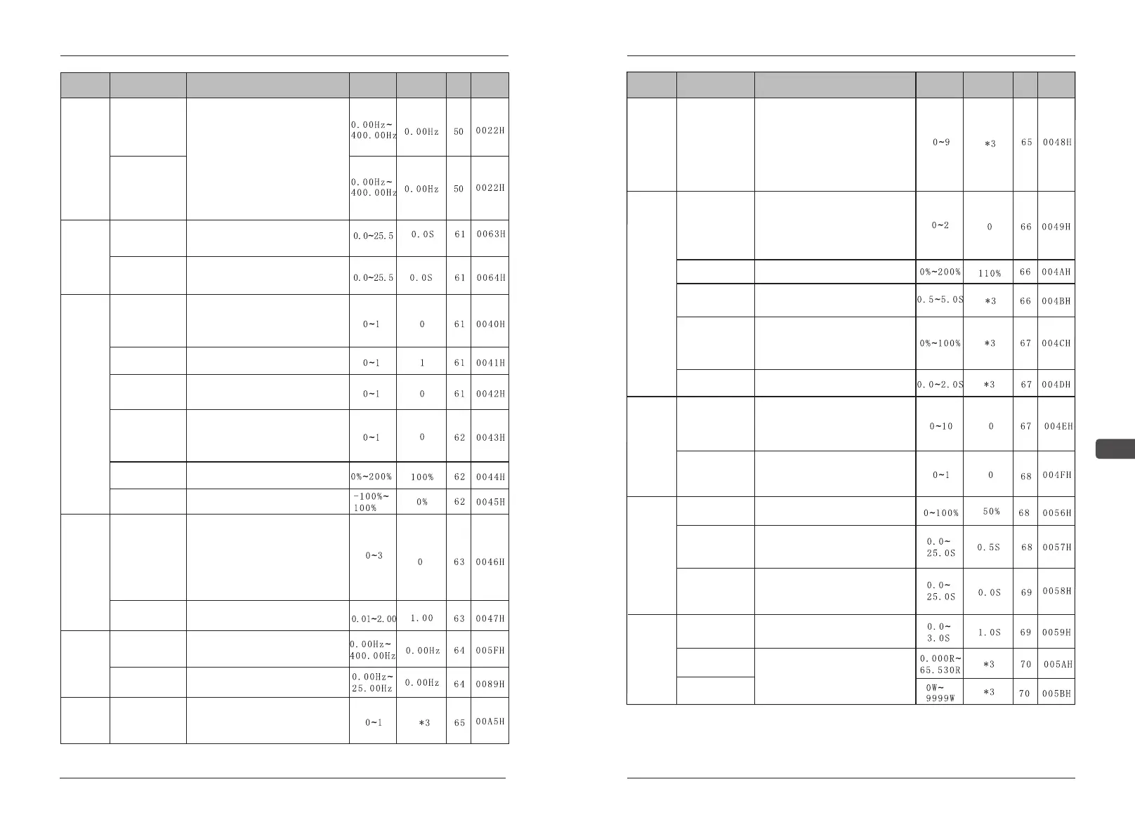
Function
Parameters
Name
Description
Setting
range
Default
Page
Address
B10 Y3 Function
14:Frequency reference loss
15:Transmission data output 1
16:Transmission data output 2
17:PID feed back lost
18:OH1 alarm
19:Running at Zero_speed
20:Output frequency reach the lower
limit Freq
21:Output frequency reach the upper
limit Freq
22:Auxiliary pump 1
23:Auxiliary pump 2
Multi-
function
output
selection
B11 Y4 Function
B12 ON-
Delay Timer
The delay time of the connect from
the input to the output
Timer
function
B13 OFF-
Delay Timer
The delay time of the disconnect
from the input to the output
B14 Master
analog
input selection
-FV or FI
terminal
0:The main Fre order is the analog
terminal FV,0~10V
1: The main Fre order is the analog
terminal FI,4~20mA
Function
selections
of
frequency
command
B15 Aux. Analog
input selection
0: 0~10V input
1: 4~20mA input(SW1-1 is on)
B16 Frequency
retention
0: Retained in frequency reference
A27
1: Not retained after power-down
B17 Operation
method for
frequency
reference loss
detection
0: No detection
1: Continue to run
B18 Terminal
FV gain
Unit:1%
B19 Terminal
FV bias
Unit:1%
Function
selections
of
analog
output
B20 FMA
funciion
0:Output Frequency(10V is the max.
Frequency)
1:Output current(10V is the AC drive
rated current)
2:Output power(10V is the AC drive
rated power)
3:DC bus voltage(10V/400V200V
grade,10V/800V400V grade)
B21 FMA Gain
Adjust the analog monitor output
gain
Frequency
agree
detection
width
B22 Frequency
detection
“frequency test” is functioning when
output frequency is over or lower
than frequency test standard B22.
B23 FAR
Amplitude
frequency test release width setting
G/P
Selection
B24 G/P
Selection
0: constant torque of G ,the
coefficient of over load is 150%1min
1: fan-type pumps of P , the
coefficient of over load is 120%1min
Function
Parameters
Name
Description
Setting
range
Default
Page
Address
Carrier
frequency
adjustment
C01 Carrier
frequency
The setting value 1,2,4-6:
The carrier frequency=The setting
value x 2.5KHz
The setting value 3:The carrier
frequency=8.0KHz
The seeting value 7,8,9:When it is
1~2.5KHz,,the change of the carrier
frequency is according to the output
frequency.
Power
loss
processing
and
speed
search
control
C02 Momentary
power loss ride
through method
0:Not provided
1:Continuous operation after power
recovery within 2s
2:Continuous operation after power
recovery within control logic time
(no fault output)
C03 Speed
search
C04 Miimnum
baseblock time
DC
Injection
C09 DC injection
current
100%=inverter rated current
C10 DC injection
time at stop
100%=inverter rated current
During speed searchin,set in dealing
instant power off, the minimal time
unit :0.1 s
C05 V/F
Search
Set the decreasing standard of
speed searching time V/F. During
speed searching
V/F= (V/F during common running)
×(C05).
C06 Power loss
ride through time
Set compensation instant power off.
Automatic
retry
C07 Automatic
retry attempts
“Set AC drive self diagnose
and restart times when error occurs.
(OC OU Uu1 GF)
C08 Fault
contact selection
during
automatic retry
0:Closed during fault retry
1:Open during fault retry
Set the DC braking time when AC
drive starts.
If set to be “0.0S”, DC braking is
invalid.
C11 DC injection
time at start
Set the DC braking time when AC
drive starts.
If set to be “0.0S”, DC braking is
invalid.
Torque
compe-
nsation
C12 Torque
compensation
gain
Normally, no adjustment is
necessary
C13 Motor phase
resistance
C14 Motor iron
loss
The moment of force data in AC
drive is pre-set already and don’t
need to change.