PORTS & JUMPERS
P1
BDM interface Factory use only – Do not connect anything to this header.
P2 (J7)
Display interface This connects, via ribbon cable, to the display, which are the
DSP1000 (EI-1000) and EI-2000-DSP.
P3 & P4
Expansion board
interface
Both headers are used to connect to expansion boards,
which are the EI-2000-IO and EI-2000-EXP.
J1 & J2
Sense connections Local or remote sense selection shunts.
J3
Instrument
selection
This selects an EI-1000, EI-2000 or EI-4000 instrument, see
below. This is set at the factory, and if this jumper is not
set properly, the meter will not function.
J4
RS485 terminator
resistor
Install a shunt to connect the 120 ohm terminator resistor to
the RS485 A & B lines.
FUSE
The fuse is a ½ ampere, 250VAC, 5x20mm, time-lag fuse. Do not use any other rating.
VOLTAGE SELECT SWITCH (S2)
The voltage selection switch, located on the EI-2000S-CPU, selects the 115V or 230V range.
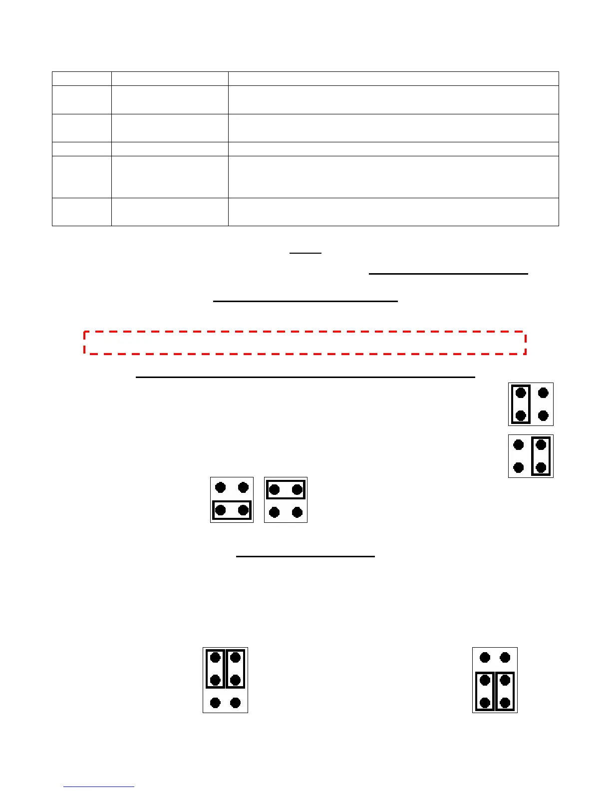
EI-1000 & EI-2000 METER SELECTION HEADER SHUNT (J3)
Connect J3-3 and J3-4 to select an EI-2000 meter; the display is the EI-2000-DSP.
Connect J3-1 and J3-2 to select an EI-1000 meter; the display is the DSP1000.
Invalid shunt positions:
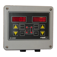
REMOTE SCALE SENSE
Single channel EI-100 e remote sense conn
error of the cable voltage drop, minute thermal errors of the connections and wire
temperature coefficients. The remote sense must be used if intrinsically-safe barriers are
being used. Do not use remote sense on the EI-2000 meter or EI-1000 multi-channel
applications.
Disabled (local sense) Enabled (remote sense)
0 meters can utilize th ections. This minimizes the
NOTE: DO NOT SELECT THE VOLTAGE WHILE THE METER IS POWERED!