H2 16-PIN
CONNECTOR
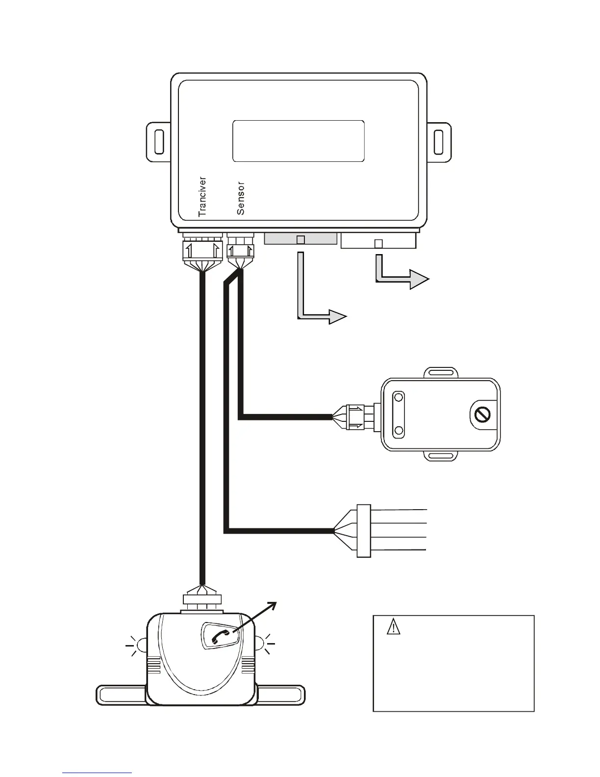
Plug-in dual stage
shock sensor
R.F A ntenna
Antenna
Extend the whole wire, align it
with the intersection of dashboard
and the front window glass.
Keep it away from the metal at
least 5 centimeter to have the
best receiving condition.
Blue LED
indicator
Blue LED
indicator
Call switch
WIRING DIAGRAM
Main control unit
H1 12-PIN
CONNECTOR
2 nd stage (-) trigger
1 st stage(-) trigger
- Ground
+12V DC output
Green
Blue
Black
Red
External Ultra sonic &
micro-wave sensor port
Dual-stage
Shock Sensor
H1
H2
Antenna module FSK/868Mhz