9
Instruction Leaet IL01301051E
effective September 2013
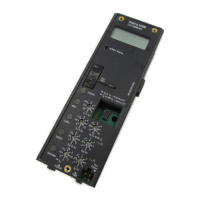
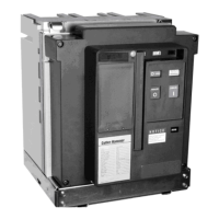
Operating Manual for Series NRX
Trip Units - Digitrip™ 520/520M
EATON www.eaton.com
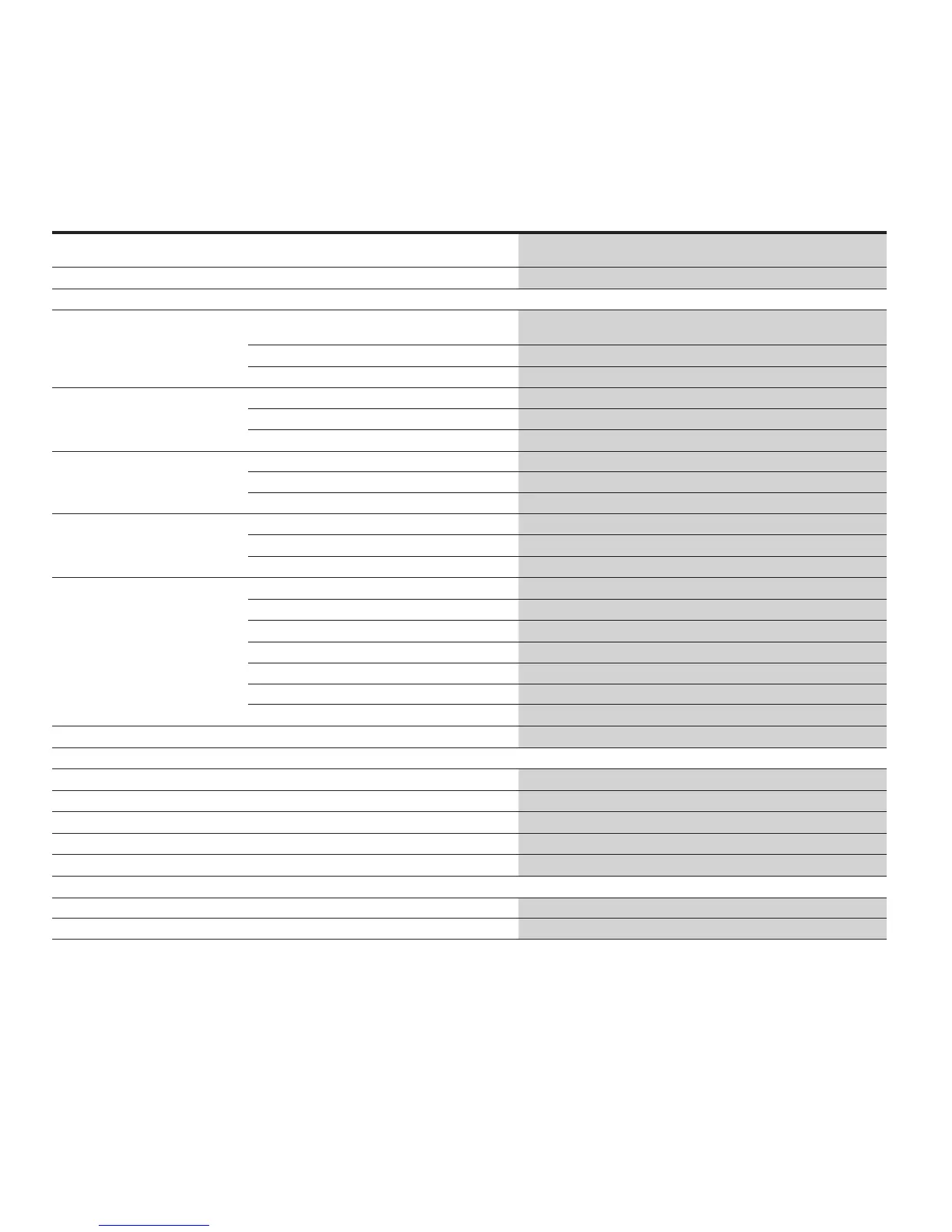
Table 4. Technical Data
Digitrip 520 LI
System Protection
Digitrip 520 LSI(G)
Selective Protection
Digitrip 520M
Universal Protection
Ampere range NF frame 200-1600A
RF frame 800- 4000A
NF frame 200-1600A
RF frame 800- 4000A
NF frame 200-1600A
RF frame 800- 4000A
RMS sensing
l l l
Protection and coordination
General Ordering style options LI LSI, LSIG MLSI, MLSIG, MLSIA,
MRLSI, MRLSIG, MRLSIA
Rating plug (I
n
)
l l l
Overtemperature trip
l l l
Long delay protection (L) Long delay pickup (0.5 – 1.0) x I
n
(0.5 – 1.0) x I
n
(0.5 – 1.0) x I
n
Long delay time t
r
at 6 x I
r
2 – 24 s 2 – 24 s 2 – 24 s
Long delay thermal memory
l l l
Short delay protection (S) Short delay pickup - (2 - 10) x I
r
(2 - 10) x I
r
Short delay time t
sd
- 100 – 500 ms 100 – 500 ms
Zone Selective Interlocking ZSI - optional optional
Instantaneous protection (I) Instantaneous pickup (2 - 12) x I
n
(2 - 12) x I
n
(2 - 12) x I
n
Off position -
l l
Making current release
l l l
Option earth fault protection (G) Earth fault option -
l l
Earth fault alarm - -
l
Earth fault pickup -
(0.25 - 1.0) x I
n
(0.25 - 1.0) x I
n
Earth fault delay t
g
, I
2
t @ 0.625 x (I
n
) - 100 – 500 ms 100 – 500 ms
Ground (earth) fault delay t
g
, flat characteristic curve - 100 – 500 ms 100 – 500 ms
Zone Selective Interlocking ZSI - optional optional
Ground fault memory -
l l
Neutral protection
l l l
System diagnostics
Status/long pickup LED
l l l
High load alarm/alarm contacts - -
l
Cause of trip LEDs
l l l
Magnitude of trip information - -
l
Remote ground trip/alarm contacts - -
l
System metering
Digital display - - 4 character LCD
Maintenance Mode (ARMS) - - optional
I
n
= rating plug = rating of current sensors
I
r
= Long delay pickup setting
Requires 24 Vdc auxiliary voltage input (LSIG-ground trip alarm, LSIA ground alarm only).
Limited to1200 A for UL
®
rating
Four Cause of Trip LEDs: L, S, I, G. Current Release trip is indicated by the red instantaneous LED:
• Orange Instantaneous LED indicates rating plug trip
• Orange Long Delay LED indicates temperature trip
• Red or orange LED status indicates internal trip unit or circuit breaker diagnostic problem detected.
Requires 24 Vdc auxiliary voltage input and LSI style.