98 Eaton 9395XC UPS 1200kW/1200kVA, 1350kW/1350kVA or 1500kW/1500kVA 164001079—Rev 01
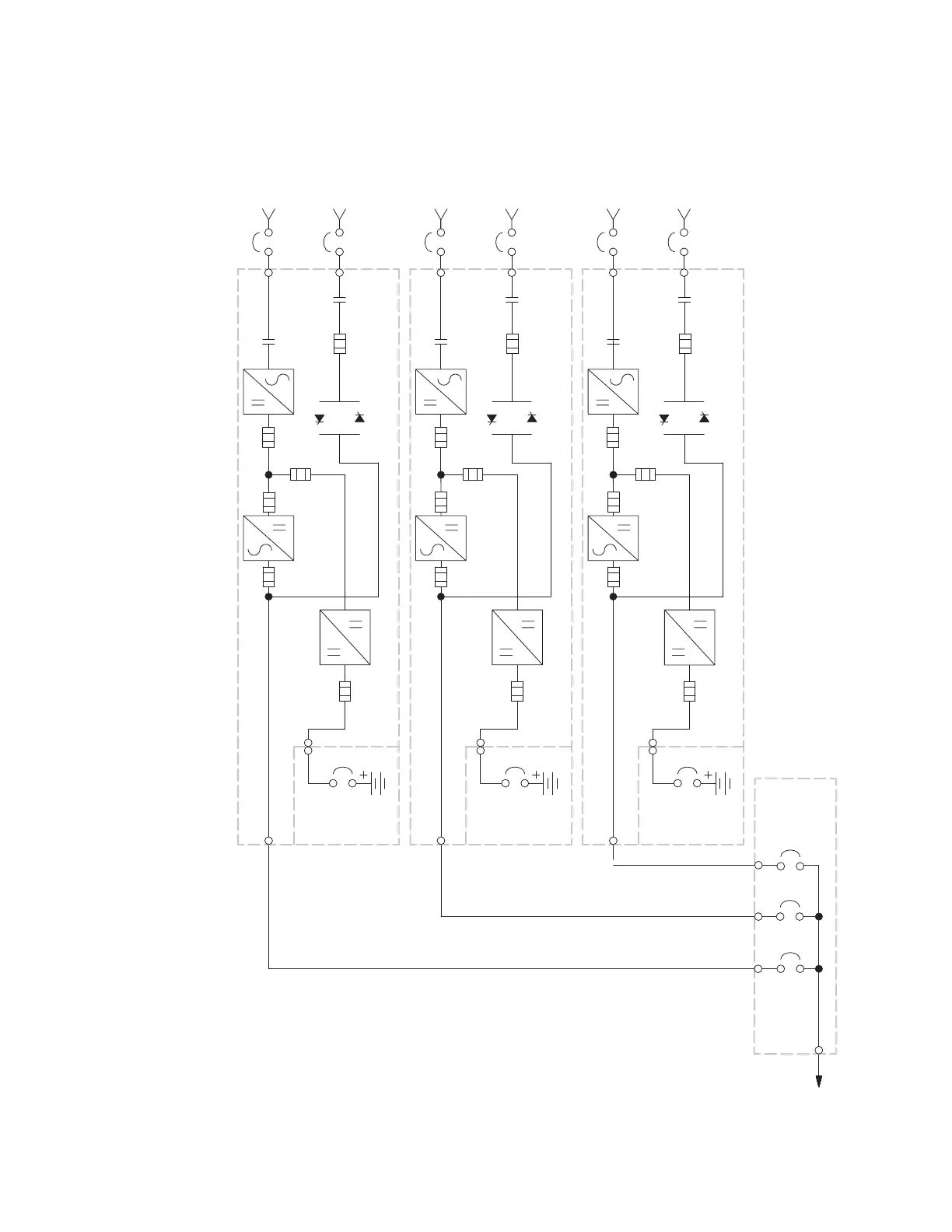
Figure 55. Typical Distributed Bypass System -Continuous Static Switch, 2+1 and 3+0 Configurations
Battery Breaker
Battery
Converter
Inverter
Rectifier
K1
Fuse
Fuse
E6
E7
E8
E1
E2
E3
UPS 1
A B
TIE
CABINET
E
AC Output to
Critical Load
E4, E5
BATTERY SYSTEM
MOB 1
MOB 2
MOB 3
(Not supplied
with the UPS)
C
E9
E10
E11
D
Battery Breaker
Battery
Converter
Inverter
Rectifier
K1
Fuse
Fuse
E6
E7
E8
E1
E2
E3
UPS 2
A B
E4, E5
BATTERY SYSTEM
(Not supplied
with the UPS)
C
E9
E10
E11
D
Battery Breaker
Battery
Converter
Inverter
Rectifier
K1
Fuse
Fuse
E6
E7
E8
E1
E2
E3
UPS 3
A B
E4, E5
BATTERY SYSTEM
(Not supplied
with the UPS)
C
E9
E10
E11
D
*
****
*
A – AC Input to UPS Rectifier
B – AC Input to Bypass
C – DC Input from Battery
D – UPS AC Output to Tie Cabinet
E – Output to Critical Load
* – Overcurrent Protection supplied by customer
*
Fuse Fuse Fuse
(optional)
K5
Fuse
(optional)
K5
Fuse
(optional)
K5
Fuse
Static
Switch
Static
Switch
Static
Switch
Fuse Fuse
Fuse
FuseFuseFuse
Understanding UPS Operation

 Loading...


