L
Laurie JacksonSep 10, 2025
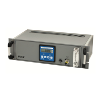
What to do if Eaton Diagnostic Equipment mode will not leave OOS Block Alarms?
- KKyle WoodSep 10, 2025
If the Eaton Diagnostic Equipment mode will not leave OOS Block Alarms, first set the target mode to something other than OOS. If this doesn't work, try restarting the device by setting RESTART to Processor. Also, ensure that FEATURES_SEL has Alerts enabled by enabling the report bit, and set LIM_NOTIFY equal to MAX_ NOTIFY. If the block error persists, it could indicate a memory failure or features notification issue, and you should call the factory for assistance.