AD 33-855-4
Page 57
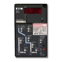
10.3
ldentification of
Trip Unit,
Breaker, and
Switchgear
Cell
Your Digitrip
RMS Retrofit
Kit includes
identifica-
tion
labels for the
Digitrip RMS
Trip
Unit,
the
Breaker
Element Faceplate,
and the inside
of the
Switchgear
Cell
Door. lt is
important to identify
all
three, especially
when the Trip Unit
has a
PowerNet address
(Models
810
& 910 only).
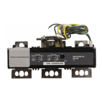
10.4
The Power
Relay Module
(ATR)
RMS
610, 810, & 910
Retrofit Kits
include the
Power
Relay Module
(ATR),
which is mounted
integral to
the RMS Trip Unit.
The ATR input
and
output signals
are extracted
from the
Trip Unit Plug
J4
through
the External Harness
as shown
in
Figure
12-9. The Breaker
External
Harness
plugs
to the Cell Harness
Assembly,
which includes
provisions
for external wiring connections
as
shown
in Figure 6-1
. Figure 10-8 shows
typical
ATR 120
VAC source input
and dry contact
alarm
output
connections
for remote alarm
indication.
10.5 Communications
and
PowerNet
RMS
810 &
910 Retrofit
Kits include communica-
tions capability
when Used
with
Cutler-Hammer's
PowerNet
System.
Each RMS
Trip Unit includes
an
lntegrated Communications
Chip
that
permits
the
extraction
of
Trip Unit data
and the
implementation
of Breaker
close and
trip commands
from a
remote
master computer.
Communication
is accomplished
from
the Trip Unit
to the master computer
via radio
frequency
signal
over a
twisted
pair
communica-
tions network.
The communications
signal
(COMM1
and COMM2)
are extracted
from
Trip Unit
Plug J3
through
the External Harness
as shown
in
Figure
12-10.
The Breaker
External Harness
plugs
to the Cell
Harness
Assembly, which
includes
provisions
for external
wiring
connections as
shown in
Figure 7-1
. Figures 1 0-9
through 1 0-12
show
typical Cell
wiring
provisions
if the
PowerNet
computer
close
feature
is to be utilized.
TYPICAL IBM OR
IBM COI\-,IPATIBLE
COI\4PUTEB
ASSFMBLIES
ELECTBONIC
MOTOB
(AEl\rl)
o
lEloldln
CUT-OFF SHIELD
AT
DEVICE
-
DO
NOT GBOUND
BAUD BATE
AND
3 DIGIT
NCO[4
ADDBESS
VIEW
A
O
Feferio circuit breaker connecl
o. dagrams referenced
in Secton 6 for acilai connections
O
i,lodular te eph one co.neclor,Type
RJ11, supplied
by useL
O
Ground shieldi.q al computer
and AEM
(cable
lo
P1 only)as shown.where
devices arc daisv-chained
nlerconneci shield ng, bul
do.ol
ground
lhe connecllon.
O
1/2 watl ca6on
resislor required al iasl breake. SeeT.D.17_5r3.
Fig.
10-7 Terminating
Resistor Location
Fifective
g/01
ElT.il
 Loading...