All programming, information display and general trip unit
access is accomplished through the use of one or more of
the following:
1. Hand Held Programmer
2. Breaker Interface Module
3. Remote computer
The breaker tripping system includes a power relay module
to provide power for the communication function and relay
outputs for alarming (Figure 5). Refer to I.L. 29C891 for more
detailed information on Digitrip OPTIM 750 Trip Units.
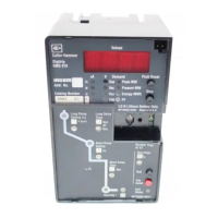
4.7 Digitrip OPTIM 1050
The OPTIM 1050 Trip Unit provides all the same basic sys-
tem protection features outlined in Section 4.6 for OPTIM
750. In addition, OPTIM 1050 Trip Units are capable of pro-
viding data on power quality and permit energy monitoring.
Energy Monitoring
1. Peak demand (kW)
2. Present demand (kW)
3 Forward energy (kWh)
4. Reverse energy (kWh)
5. Total energy (kWh)
6. Power factor
Power Quality
1. Percentage harmonic content
2. Total harmonic distortion (THD)
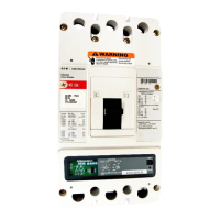
Terminal
Block
Typical
Current
Sensor
Rating
Plug
Protection
Function
Settings
Typical Trip Unit
Trip Actuator
Typical DSII Type
Circuit Breaker
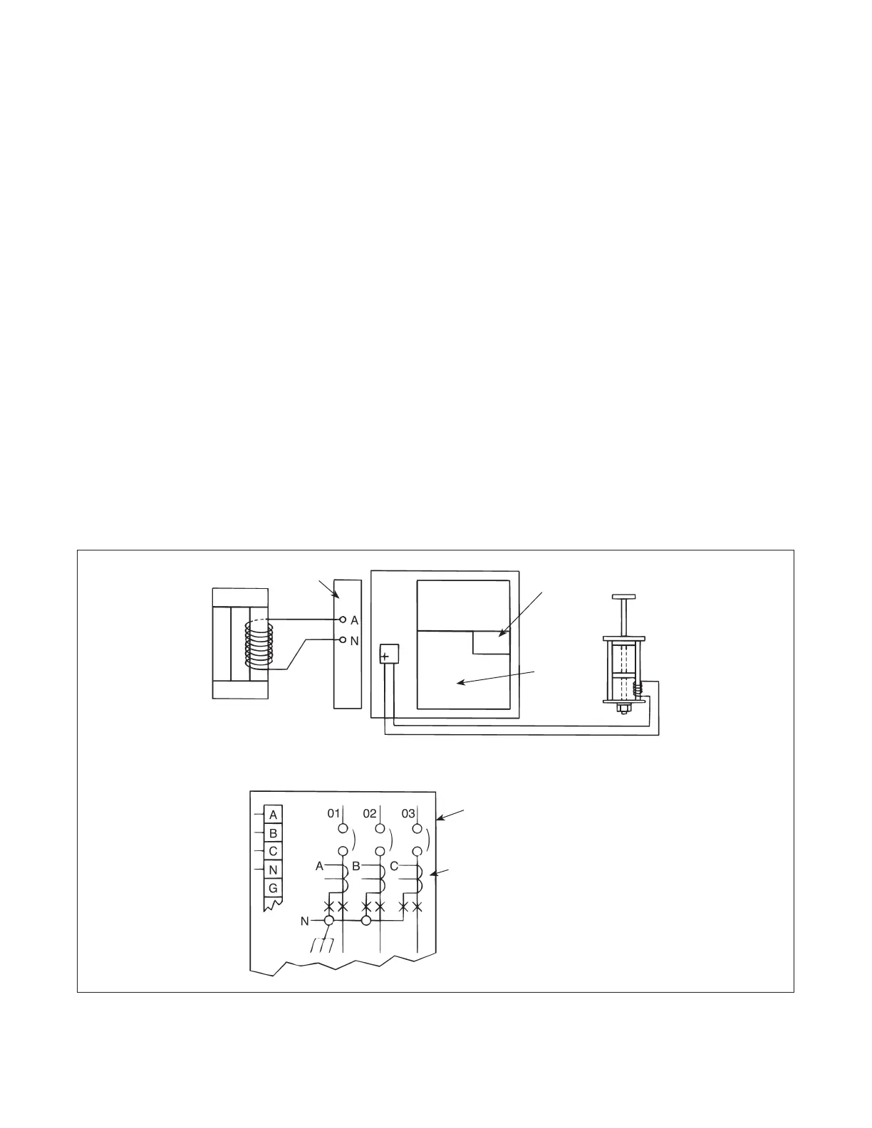
Sensors
** Alternate ground locations
may be required to meet
installation requirements
Figure 6 Typical Schematic Diagram of Basic Connections in Tripping System of DSII Circuit Breaker
Effective July 2010
Instructional Leaflet IL8700C39-04
11
EATON CORPORATION www.eaton.com
 Loading...