Effective July 2010
Instructional Leaflet IL8700C39-04
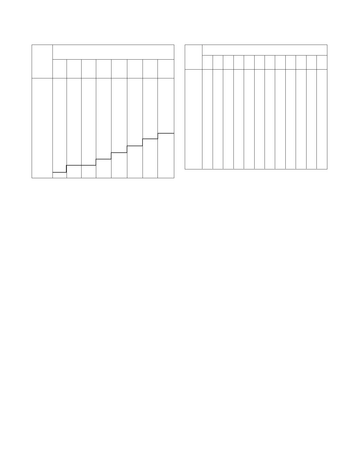
Installed Pick-up (Dial) Setting
Rating Amperes j
Plug
Amperes Ak Bk Ck Dk Ek F H K
(In)
100 25 30 35 40 50 60 75 100
200 50 60 70 80 100 120 150 200
250 63 75 88 100 125 150 188 250
300 75 90 105 120 150 180 225 300
400 100 120 140 160 200 240 300 400
600 150 180 210 240 300 360 450 600
800 200 240 280 320 400 480 600 800
1000 250 300 350 400 500 600 750 1000
1200 300 360 420 480 600 720 900 1200
1600 400 480 560 640 800 960 1200 1200
2000 500 600 700 800 1000 1200 1200 1200
2400 600 720 840 960 1200 1200 1200 1200
3200 800 960 1120 1200 1200 1200 1200 1200
4000 1000 1200 1200 1200 1200 1200 1200 1200
5000 1200 1200 1200 1200 1200 1200 1200 1200
j Except as noted, tolerances on pick-up levels are ±10% of values
shown in chart.
k Ground fault pick-up levels shown are nominal values when
tested with external control power present. Without external con-
trol power, such as is the case with the Digitrip RMS 510, ground
pick-up levels may exceed these values and be as high as the
value shown for the “E” setting of that particular rating plug.
l Not applicable to Digitrip OPTIM. The ground fault pick-up setting
is read directly from Digitrip OPTIM. These settings range from
25% to 100% of the rating plug value up to a maximum NEC
limitation of 1200 amperes.
Depending upon the installation requirements, alternate
ground fault sensing schemes may be employed. Two
popular methods include: Ground return and zero sequence.
Either method can be employed with the Digitrip Trip Unit.
For either type application, a ring type current sensor, as il-
lustrated in Figure 7, is normally employed. For ground return
sensing, the sensor is arranged to have the system “main
bonding jumper” pass directly through the sensor. For zero
sequence sensing methods, all phase and neutral conduc-
tors must pass through the sensor.
Where multi-conductor cables are required for a particular
circuit and the window opening in a single BYZ sensor is too
small to accommodate all cables, separate BYZ sensors may
be installed on each set of cables
(3 phase, neutral) and the secondaries connected in paral-
lel. (Note: Proper polarity markings must be observed.) The
resultant secondary current signal will be equivalent to a
single BYZ sensor.
The BYZ current sensor styles shown in Figure 7 are avail-
able for all previously mentioned applications. When either
style sensor is used, the ground fault values shown in Table
3 are not applicable and the values shown in Table 4 should
be used. One of the reasons for using the BYZ current
sensors is to improve the level of sensitivity. This being the
case, then the ground fault functional pick-up setting should
be placed on position “A.” The sensitivity of the ground ele-
ment for this kind of arrangement will depend upon the ratio
of the BYZ sensor used.
A variety of utilization schemes are available utilizing each of
the above methods of ground fault sensing. Therefore, the
individual installation requirements must be closely studied
to insure proper application.
5.5 Current Sensors
The three current sensors installed in the circuit breaker are
located at the rear of the circuit breaker on the lower studs.
The location is shown in Figure 3-1 of l.B. 694C694. They
produce an output signal proportional to the load current
and furnish the Digitrip Trip Assembly with the intelligence
and energy to trip the circuit breaker when the time-current
conditions exceed the functional protection settings.
The continuous current rating for any frame size breaker can
be changed by changing the rating plug. A complete tabula-
tion of available current sensors and rating plugs is given in
Ratings Sensor Ratings - Amperes
Plug
Amps 200 300 400 600 800 1200 1600 2000 2400 3200 4000 5000
100 6.3
200 12.5 8.3 6.3
250 10.4 7.8
300 12.5 9.4 6.3
400 12.5 8.3 6.3
600 12.5 9.4 6.3
800 12.5 8.3 6.3
1000 10.4 7.8 6.3
1200 12.5 9.4 7.5 6.3
1600 12.5 10 8.3 6.3
2000 12.5 10.4 7.8 6.3
2400 12.5 9.4 7.5
3200 12.5 10 8.0
4000 12.5 10.0
5000 12.5
j Except as noted, tolerances on pick-up levels are ±10% of values
shown in chart.
k Ground fault pick-up levels shown are nominal values when
tested with external control power present. Without external
control power such as is the case with the Digitrip RMS 510 trip
unit, ground pick-up levels can vary between the minimum and
maximum values shown for each sensor rating.
l For BYZ (100/5) sensor, multiply above values by two.
14
EATON CORPORATION www.eaton.com
Table 3 Ground Current Pick-up Settings l
Table 4 Approximate Ground Fault Pick-up Amperes Using BYZ
(50/5) Sensor and “A” Position Setting on Ground Fault Pick-up
j k l
 Loading...