6
WIRING
All wiring to the ratemeter is done via rear terminal, de-pluggable connectors. Up to
five headers accept the wired connectors on the ratemeter. All units have at least two
headers, power input and signal input. Any combination of three additional circuit
boards with headers may be installed. These option boards are relay output, RS 485
serial communications, and analog retransmission. The option boards occupy spe-
cific locations in the ratemeter and are not interchangeable.
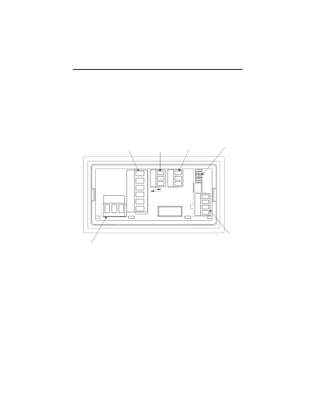
Rear Terminal Layout
Relay
Output
RS485
Communications
Analog
Output
DIP Switch
Signal Input
Power Input
2 Terminals for DC
Powered Units
3 Terminals for
AC Powered Units
Durant
®
1
1
1
11
WIRING

 Loading...