EasyManuals Logo

Eaton ELCB Series User Manual

Eaton ELCB Series
9 pages
To Next Page IconTo Next Page
To Previous Page IconTo Previous Page
Page #6 background imageLoading...
Page #6 background image
- 5 -
1
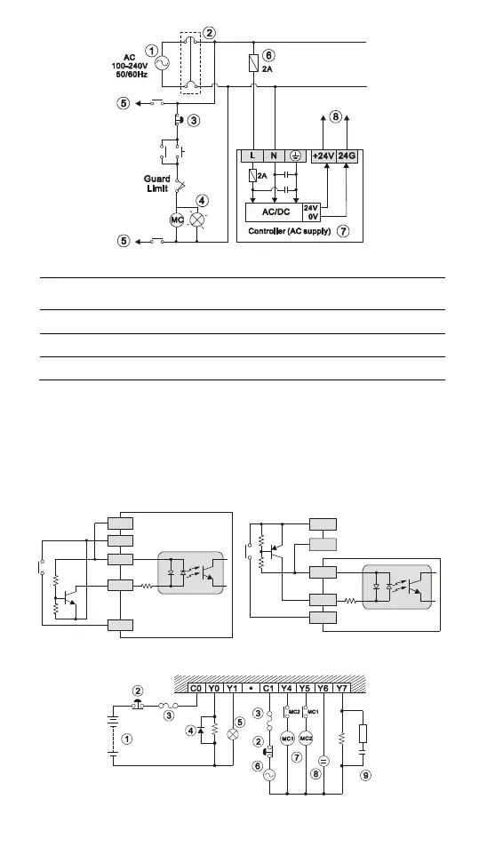
AC power supply:100 ~ 240VAC, 50/60Hz
2
Breaker
3
Emergency stop: This button cuts off the system power supply when accidental
emergency takes place.
4
Power indicator
5
AC power supply load
6
Power supply circuit protection fuse (2A)
7
ELCB (main processing unit)
8
DC power supply output: 24VDC
I/O Point Wiring
There are 2 types of DC inputs, SINK and SOURCE. (See the example
below. For detailed wiring configuration, please refer to the specification of
each controller.)
DC Signal IN SINK mode
Input point loop equivalent circuit
DC Signal IN SOURCE mode
Input point loop equivalent circuit
24G
+24V
S/S
X0
X1
+24V
24G
S/S
X0
X1
Relay (R) output circuit wiring

Questions and Answers:

Question and Answer IconNeed help?

Do you have a question about the Eaton ELCB Series and is the answer not in the manual?

Eaton ELCB Series Specifications

General IconGeneral
BrandEaton
ModelELCB Series
CategoryController
LanguageEnglish

Related product manuals