- 6 -
Emergency stop: Use an external switch
Fuse: Use 5 to 10A fuse at the shared terminal of output contacts to protect the
output circuit
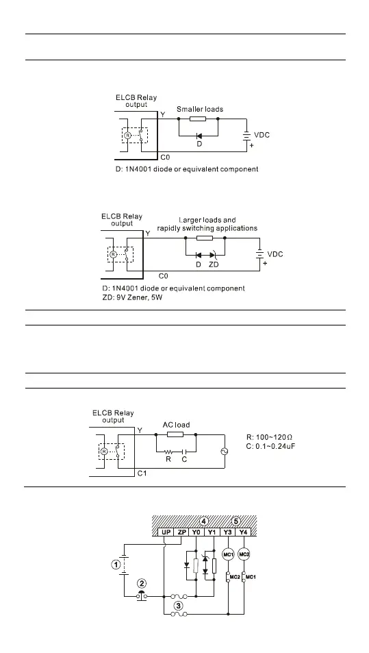
Transient voltage suppressor: To extend the life span of relay contacts.
1. Diode suppression of DC loads: Used for smaller loads.
2. Diode + Zener suppression of DC load: Used with larger loads, and for rapidly
switching applications.
Incandescent light (resistive load)
Mutually exclusive output: For example, Y4 and Y5 control the forward running and
reverse running of the motor, forming an interlock for the external circuit, together
with the ELCB internal program, to ensure safe operation in case of any unexpected
errors.
Suppressor: To reduce the interference on AC load (Figure 10)
Transistor (T) output circuit wiring

 Loading...


