- 7 -
The output of the transistor module is “open collector”. If Y0/Y1 is set to pulse
output, the output current has to be 0.05 ~ 0.5A to ensure normal operation of the
output.
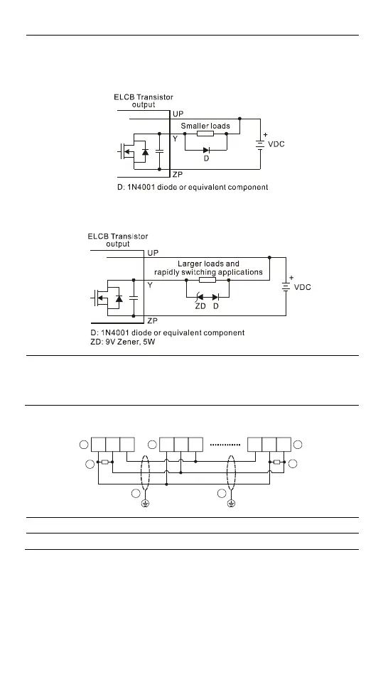
1. Diode suppression: Used with smaller loads.
2. Diode + Zener suppression: Used with larger loads, and for rapidly switching
applications.
Mutually exclusive output: For example, Y3 and Y4 control the forward running and
reverse running of the motor, forming an interlock for the external circuit, together
with the ELCB internal program, to ensure safe operation in case of any unexpected
errors.
RS-485 Wiring
D+ D- SG D+ D- SG SG D+ D-
3
4
1 2 2
3
4
Note: 1. Terminal resistors are suggested to be connected to the master, and the last
slave, with resistor value of 120.
2. To ensure communication quality, please wire using double shielded twisted
pair cable (20AWG).
3. When voltage drop occurs between the internal ground references of two
systems, connect the systems with Signal Ground point (SG) for achieving
equal potential between systems so that a stable communication can be
obtained.

 Loading...


