Do you have a question about the Eaton EX RT 7 and is the answer not in the manual?
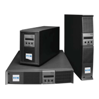
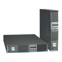
Identifies the Eaton EX RT UPS models covered in this installation and user manual.
Eaton's commitment to environmental impact through eco-design for the EX RT product lifecycle.
Guidance on how to find information within the manual, primarily by checking contents and index.
Explanation of icons used for important instructions, information, actions, and LED status.
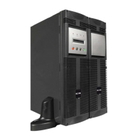
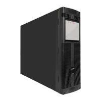
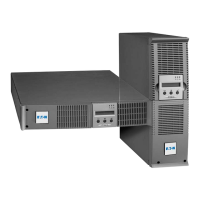
Details on UPS configurations in tower and rack mounting, including dimensions and weight.
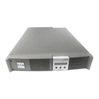
Identification and description of connectors and components on the rear panels of power and battery modules.
Overview of the front panel display and control buttons for operating the UPS unit.
Description of optional accessories like rack mounting kits, transformers, and battery extension modules.
Steps for initial power-up, UPS personalization via front panel or software.
Detailed explanation of Normal (double conversion) and Eco operating modes.
How the UPS operates on battery power, including low-battery warnings and shutdown.
Guidance on hot-swapping power and battery modules, and troubleshooting common issues.
Specifications and diagrams for the tower configuration of the UPS units.
Specifications and diagrams for mounting the UPS units in a 19-inch rack.
Diagram and labels for the power module's rear panel connectors and components.
Diagram and labels for the battery module's rear panel connectors and components.
Identification of LEDs, alphanumeric display, and buttons on the UPS front panel.
Details on installing telescopic rails and bracket systems for rack mounting.
Explanation of the transformer module's purpose for galvanic isolation or earthing arrangement changes.
Diagram showing how the transformer module connects upstream for galvanic isolation.
Information on connecting EX RT EXB modules to increase backup time up to 60 minutes.
Details on the CLA module for achieving backup times of 2 to 8 hours.
System for stacking up to 8 modules for extended backup time configurations.
Battery module with Remote Emergency Power Off (REPO) function and its circuit breaker.
Description of the extended battery cable for distant battery modules.
Instructions and diagram for unpacking the UPS power module and its accessories.
Instructions and diagram for unpacking the UPS battery module and its accessories.
List and identification of included parts such as cables, stands, rails, and documentation.
Step-by-step guide to attaching and adjusting tower stands for upright UPS placement.
Important spacing requirements and steps for upright installation.
Instructions for adjusting the orientation of the logo and control panels for rack mounting.
Procedure for mounting the heavy battery module into a rack using optional rails.
Procedure for mounting the power module into a rack using optional rails.
Step-by-step guide for sliding the UPS unit onto the installed rack rails.
Note regarding the supply of rails and mounting hardware by EATON.
Use of the rear bracket system for moving rack enclosures with UPS already mounted.
Bracket for securing the Input/Output box during hot-swapping of the power module.
Instructions for connecting the UPS to a computer via the RS232 serial port.
Details on the relay communication port, its pins, and output relay specifications.
Procedure for installing the Remote Power Off function for emergency shutdown.
Description of the EPO port for emergency power isolation with battery modules.
Guide on how to install optional communication cards into the UPS slot.
Diagrams for UPS installation with common AC inputs and galvanic isolation.
Diagrams for UPS installation with separate AC inputs and galvanic isolation.
Diagrams for UPS installation with separate AC sources and galvanic isolation.
Configuration for applications where input frequency differs from mains frequency.
Configuration for providing full redundancy (N+1) to critical loads.
Specifications for upstream circuit breakers based on UPS power rating and AC input type.
Specifications for downstream circuit breakers for output circuit protection.
Guidelines for terminal-block and earthing conductor cable sizes.
Procedure for connecting power cables to the UPS for common AC sources.
Steps for refitting the terminal block cover and tightening cable glands.
Detailed steps for connecting Normal and Bypass AC input cables separately.
Procedure for connecting output and bypass AC cables to the respective terminal blocks.
Steps for connecting AC input and output cables for the frequency converter option.
Important note: Do not connect anything to the Bypass AC terminal block for this configuration.
Procedure for connecting the battery power and detection cables to the UPS.
Diagram and instructions for connecting the galvanic isolation transformer.
Procedure for connecting the battery cable between the power module and the CLA module.
Steps for connecting the AC input cable of the CLA module and its circuit breaker.
Steps for checking circuit breakers, bypass switch, and initial power-up sequence.
Overview of UPS personalization settings available via front panel or software.
Instructions on how to enter personalization mode using the UPS front panel buttons.
Settings for cold start, forced reboot, automatic restart, sleep mode, and software control.
Configuration options for battery test, low battery signal, and deep discharge protection.
Guide to personalizing UPS settings using the Personal Solution-Pac software.
Steps to complete the startup sequence after personalization, including LED indicators.
Detailed explanation of the default Normal mode, including AC source availability scenarios.
Explanation of Eco mode benefits and operation under different AC source conditions.
Indicators and behavior when the UPS transfers to battery power due to AC source loss.
Description of the low-battery warning indicators and recommended actions.
Behavior and indicators when the UPS backup time is exhausted.
Steps for shutting down the UPS using the OFF button and circuit breakers.
Notes on load power during shutdown, frequency converter mode, and bypass AC source issues.
Common indications and corrections for issues not requiring EATON support.
Indications and actions for faults that need EATON after-sales support.
Steps to safely disconnect the power module while the load remains powered by bypass.
Confirmation that the connected equipment is powered by the Bypass AC source during replacement.
Procedure for reconnecting the power module and completing the UPS startup sequence.
Steps to safely disconnect the battery module for replacement.
Procedure for reconnecting the battery module and completing the UPS startup.
Information on technical training courses offered by EATON for product usage and maintenance.
Details on operating modes, overload behavior, and protection device selection.
Guidelines for selecting upstream circuit breakers based on UPS power rating and line current.
Time/current curves for the UPS Normal AC source circuit-breaker.
Time/current curves for UPS input and output fuses.
Voltage and frequency ranges for AC sources and load output.
Data on permissible overloads and short-circuit currents provided by the UPS.
Technical specifications for the EX RT Transformer module.
Technical details for the EX RT CLA module, including input voltage and charge current.
Information on operating temperature, battery backup time impact, and airflow.
Definitions of key terms used in the UPS manual, such as Backup time, ECO mode, and Normal mode.